I am trying to understand the interface with Arduino UNO. Can some one guide how to test this IC as per wave form
I have attached waveform for reference.
https://playground.arduino.cc/Code/ShiftRegSN74HC165N
I have connected 8 PUSH button and out put reading through Arduino.
I have modified code to understand.
MY main intention when parallel switch pressed . Serial data should be read and print the Key has pressed . Based on key press i could able to judge the values.
i.e 2^8 = 256
#define LED 13
int ploadPin        = 9;  // Load Input SH/LD
int clockEnablePin  = 8;  // CLOCK INH
int dataPin         = 11; // Serial Input SER
int clockPin        = 12; // CLOCK Input CLK
unsigned int i;

void setup()


{

    Serial.begin(9600);

    /* Initialize our digital pins...
    */
    pinMode(ploadPin, OUTPUT);
    pinMode(clockEnablePin, OUTPUT);
    pinMode(clockPin, OUTPUT);
    pinMode(dataPin, INPUT);
    pinMode(LED,OUTPUT);

    digitalWrite(clockPin, LOW);
    digitalWrite(ploadPin, HIGH);
}

void loop()
{

  for(i=0;i<=14;i++)
  {
   if(digitalRead(clockPin)==LOW)
     {
      digitalWrite(clockPin,HIGH);
      digitalWrite(clockEnablePin,HIGH);
      digitalRead(clockEnablePin);
      delay(1);

     } else
      {
         digitalWrite(clockPin,LOW);
          digitalWrite(clockEnablePin,HIGH);
             digitalRead(clockEnablePin);
          delay(1);
      }

         if(i==2)
       {
           digitalWrite(ploadPin,LOW);
           delay(2);
       }else
        {
            digitalWrite(ploadPin,HIGH);
        }


   }

       i=i++;

      if(i>=14 && i<=20)
       {
        digitalWrite(clockPin,LOW);
       }else
       if(i>=20)
       {
        i=0;
       }

/*
 if(i<=6)
       {
         digitalWrite(clockEnablePin,HIGH);
       }else
        {
          digitalWrite(clockEnablePin,LOW);
        }*/


   if(digitalRead(13)==LOW)
     {
      digitalWrite(LED,HIGH);

     } else
      {
         digitalWrite(LED,LOW);
      }


  delay(50);


}
Have you got a question ?
What happens if you run the original code ?
This code i am testing.
I have used below schmatic , In place of DIP switch i used push button.
I am trying to give random push button input. For some input it working fine.
for example
D0D1D2 LOW
D3D4D5 HIGH
D6D7D8 LOW
Attached is wave form for it.
output:
D0D1D2 HIGH
D3D4D5 LOW
D6D7D8 HIGH
if i give same input in combination the waveform wont get reflected as expected, for example if push button for D6D7D8 are pressed output QH remains LOW.
My intention is what ever switch pressed must be detected and give proper Serial out.
and also How can i read the Q0-Q8 values to convert it to Integer. I am planned to read those data to caluclate value 2^8. based on Input switch pressed equivalent value should be printed.

const int data_pin = 11; // Connect Pin 11 to SER_OUT (Serial data out) - Pin 9 (Q7) of 74HC165
const int shld_pin = 8; // Connect Pin 8 to SH/!LD (shift or active low load) - Pin 1 (!PL) of 74HC165
const int clk_pin = 12; // Connect Pin 12 to CLK (the clock that times the shifting) - Pin 2 (CP) of 74HC165
const int ce_pin = 9; // Connect Pin 9 to !CE (clock enable, active low) - Pin 15 (!CE) of 74HC165
byte incoming; // V ar iable to stor e the 8 values loaded fr om the shift r egister


void setup()
{
        // Initialize Serial to gain the power to obtain r elevant infor mation, 9600 baud
        Serial.begin(9600);
        // Initialize each digital pin to either output or input
        // We ar e commanding the shift r egister with each pin with the exception of the Serial
        // data we get back on the data_pin line.
        pinMode(shld_pin, OUTPUT);
        pinMode(ce_pin, OUTPUT);
        pinMode(clk_pin, OUTPUT);
        pinMode(data_pin, INPUT);
        // Requir ed initial states of these two pins accor ding to the datasheet timing diagr am
        digitalWrite(clk_pin, HIGH);
        digitalWrite(shld_pin, HIGH);
}


void loop()
{
      incoming = read_shift_regs(); // Read the shift r egister , it likes that
      Serial.println("\nThe incoming values of the shift register are ");
      Serial.println("D7 D6 D5 D4 D3 D2 D1 D0:");
      print_byte(incoming); // print ever y 1 and 0 that cor r elates with 8 thr ough 1 of the dip switch
      delay(1000); // Wait for some ar bitr ar y amount of time
      Serial.println(".......................................................");
 }


// This code is intended to trigger the shift r egister to gr ab values fr om its D7 - D0 inputs
byte read_shift_regs()
{
      byte the_shifted = 0; // An 8 bit number to car r y each bit value of D7 - D0
      // Trigger loading the state of the A-H data lines into the shift r egister
      digitalWrite(shld_pin, LOW);
      delayMicroseconds(5); // Requir es a delay her e accor ding to the datasheet timing diagr am
      digitalWrite(shld_pin, HIGH);
      delayMicroseconds(5);
      // Requir ed initial states of these two pins accor ding to the datasheet timing diagr am
      digitalWrite(clk_pin, HIGH);
      digitalWrite(ce_pin, LOW); // Enable the clock
      // Get D7 ~ D0 values
      // The function shiftIn() shifts in a byte (8-bit) of data one bit at a time star ing fr om either the most (leftmost) or the least (r ightmost) significant bit.
      the_shifted = shiftIn(data_pin, clk_pin, MSBFIRST);
      digitalWrite(ce_pin, HIGH); // Disable the clock
      return the_shifted;
}


void print_byte(byte val)
{
        // This par t is a bit differ ent fr om the Spar kfun code.
        // Refer ence: The Quick Refer ence section of Bit Math Tutor ial http://playgr ound.ar duino.cc/Code/BitMath on how to isolate individual bit.
        Serial.print(val >> 7 & 1, BIN); // print 7th bit of val
        Serial.print(" ");
        Serial.print(val >> 6 & 1, BIN); // print 6th bit of val
        Serial.print(" ");
        Serial.print(val >> 5 & 1, BIN); // print 5th bit of val
        Serial.print(" ");
        Serial.print(val >> 4 & 1, BIN); // print 4th

         Serial.print(" ");
        Serial.print(val >> 3 & 1, BIN); // print 3th

        Serial.print(val >> 2 & 1, BIN); // print 2th bit of val
        Serial.print(" ");
        Serial.print(val >> 1 & 1, BIN); // print 1th bit of val
        Serial.print(" ");
        Serial.println(val >> 0 & 1, BIN); // print 0th bit of val
        // the above code can be wr itten as follow
        int i;

        for (int i = 8; i > 0; i--)
        {
        Serial.print(val >> (i - 1) & 1, BIN);
        Serial.print(" ");
        }
        Serial.print("\n");
}
Let me Know how can i read status of DIP Switch/ Push button with This circuit.
I would like to read status of switch and Then calculate the Int value.
I would like to read status of switch and Then calculate the Int value.
Is that not what the code in the page you linked to in your original post does ?
I am testing example code from arduino itself. The code as below.
I am using single IC for Testing
/*
 * SN74HC165N_shift_reg
 *
 * Program to shift in the bit values from a SN74HC165N 8-bit
 * parallel-in/serial-out shift register.
 *
 * This sketch demonstrates reading in 16 digital states from a
 * pair of daisy-chained SN74HC165N shift registers while using
 * only 4 digital pins on the Arduino.
 *
 * You can daisy-chain these chips by connecting the serial-out
 * (Q7 pin) on one shift register to the serial-in (Ds pin) of
 * the other.
 *
 * Of course you can daisy chain as many as you like while still
 * using only 4 Arduino pins (though you would have to process
 * them 4 at a time into separate unsigned long variables).
 *
*/

/* How many shift register chips are daisy-chained.
*/
#define NUMBER_OF_SHIFT_CHIPS   1

/* Width of data (how many ext lines).
*/
#define DATA_WIDTH   NUMBER_OF_SHIFT_CHIPS * 8

/* Width of pulse to trigger the shift register to read and latch.
*/
#define PULSE_WIDTH_USEC   5

/* Optional delay between shift register reads.
*/
#define POLL_DELAY_MSEC   1

/* You will need to change the "int" to "long" If the
 * NUMBER_OF_SHIFT_CHIPS is higher than 2.
*/
#define BYTES_VAL_T unsigned int

int ploadPin        = 8;  // Connect Pin 8 to SH/!LD (shift or active low load) - Pin 1 (!PL) of 74HC165
int clockEnablePin  = 9;  // Connect Pin 9 to !CE (clock enable, active low) - Pin 15 (!CE) of 74HC165
int dataPin         = 11; // Connect Pin 11 to SER_OUT (Serial data out) - Pin 9 (Q7) of 74HC165
int clockPin        = 12; // Connect Pin 12 to CLK (the clock that times the shifting) - Pin 2 (CP) of 74HC165

BYTES_VAL_T pinValues;
BYTES_VAL_T oldPinValues;

/* This function is essentially a "shift-in" routine reading the
 * serial Data from the shift register chips and representing
 * the state of those pins in an unsigned integer (or long).
*/
BYTES_VAL_T read_shift_regs()
{
    long bitVal;
    BYTES_VAL_T bytesVal = 0;

    /* Trigger a parallel Load to latch the state of the data lines,
    */
    digitalWrite(clockEnablePin, HIGH);
    digitalWrite(ploadPin, LOW);
    delayMicroseconds(PULSE_WIDTH_USEC);
    digitalWrite(ploadPin, HIGH);
    digitalWrite(clockEnablePin, LOW);

    /* Loop to read each bit value from the serial out line
     * of the SN74HC165N.
    */
    for(int i = 0; i < DATA_WIDTH; i++)
    {
        bitVal = digitalRead(dataPin);

        /* Set the corresponding bit in bytesVal.
        */
        bytesVal |= (bitVal << ((DATA_WIDTH-1) - i));

        /* Pulse the Clock (rising edge shifts the next bit).
        */
        digitalWrite(clockPin, HIGH);
        delayMicroseconds(PULSE_WIDTH_USEC);
        digitalWrite(clockPin, LOW);
    }

    return(bytesVal);
}

/* Dump the list of zones along with their current status.
*/
void display_pin_values()
{
    Serial.print("Pin States:\r\n");

    for(int i = 0; i < DATA_WIDTH; i++)
    {
        Serial.print("  Pin-");
        Serial.print(i);
        Serial.print(": ");

        if((pinValues >> i) & 1)
            Serial.print("HIGH");
        else
            Serial.print("LOW");

        Serial.print("\r\n");
    }

    Serial.print("\r\n");
}

void setup()
{
    Serial.begin(9600);

    /* Initialize our digital pins...
    */
    pinMode(ploadPin, OUTPUT);
    pinMode(clockEnablePin, OUTPUT);
    pinMode(clockPin, OUTPUT);
    pinMode(dataPin, INPUT);

    digitalWrite(clockPin, LOW);
    digitalWrite(ploadPin, HIGH);

    /* Read in and display the pin states at startup.
    */
    pinValues = read_shift_regs();
    display_pin_values();
    oldPinValues = pinValues;
}

void loop()
{
    /* Read the state of all zones.
    */
    pinValues = read_shift_regs();

    /* If there was a chage in state, display which ones changed.
    */
    if(pinValues != oldPinValues)
    {
        Serial.print("*Pin value change detected*\r\n");
        display_pin_values();
        oldPinValues = pinValues;
    }

    delay(POLL_DELAY_MSEC);
}
I have given input as per datasheet the waveform i am getting not matches the out put.
Input given as per datasheet refer page no 12:
CIrcuit i designed for testing
I have attached output for above code . kindly let me how exactly i can create as per datasheet waveform
channels.txt (3.18 KB)
I have tested above code . Its not even generating clock pulse.
Hi,
Can you add this Serial.println to your void loop()
void loop()
{
  /* Read the state of all zones.
  */
  pinValues = read_shift_regs();
  Serial.println(pinValues);
  /* If there was a chage in state, display which ones changed.
  */
  if (pinValues != oldPinValues)
  {
    Serial.print("*Pin value change detected*\r\n");
    display_pin_values();
    oldPinValues = pinValues;
  }

  delay(POLL_DELAY_MSEC);
}
It will print what you have read from the HC165, before displaying it in columns.
Can you please post a picture of your project so we can see your layout?
Are you using protoboard?
If so, are the red and blue/black power lines down the sides a continuous line, if they are broken in the middle then they are not continuous conductor strips.
Thanks.. Tom.. 
Hi,
From the timing diagram, the bits are clocked on the rising edge of the clock pulse.
Data is read on the falling edge.
The Blue is rising clock, and Red is falling.

The reference page for shiftIn function says;
If you’re interfacing with a device that’s clocked by rising edges, you’ll need to make sure that the clock pin is low before the first call to shiftIn() ,eg. with a call to digitalWrite(clockPin,LOW)
Your code leaves the clock HIGH.
You need to clock LOW before shiftIn function..
Hope this helps..
Tom..
why not use SPI instead of devising clock pulses?
#include<SPI.h>
/*SPI pins (Ard UNO)
   MOSI 11  //OUTPUT: not used here
   MISO 12  //INPUT: connect to Qh on 74HC165
   SCK  13  //connect to CLK on 74HC165
   SS (default) 10 // connect to CLK_INH pin on 74HC165
*/
#define SH_LD 9 //connect to Shift/Load pin on 74HC165
#define T_Poll 100 // register polling period (ms)

unsigned long oldtime;
void setup() {
  //Initialise Serial
  Serial.begin(250000);

  //initalise SPI
  SPI.beginTransaction(SPISettings(SPI_CLOCK_DIV2, MSBFIRST, SPI_MODE1)); //SPI_MODE1: read data bit on clock falling edge

  //initialise control pins
  pinMode(SH_LD, OUTPUT);
  digitalWrite(SH_LD, HIGH);
  digitalWrite(SS, HIGH);

  oldtime = millis();

}

void loop() {

  if (millis() - oldtime > T_Poll) {
    //load data inputs into register
    digitalWrite(SH_LD, LOW);
    delayMicroseconds(2); //arbitrary delay
    digitalWrite(SH_LD, HIGH);

    //read register
    digitalWrite(SS, LOW);
    uint8_t reg = SPI.transfer(0);
    digitalWrite(SS, HIGH);

    //print status to serial monitor as binary string
    Serial.println(reg, BIN);

    oldtime = millis();
  }

}
Please send me full code .SO i can tested out and give you exact output.
I have tried with arduino forum code. But i haven't got answer as per datasheet.
If you share me completed code i can send Serial output window along with clock cycle diagram
TomGeorge:
Hi,
Can you add this Serial.println to your void loop()
void loop()
{
/* Read the state of all zones.
/
pinValues = read_shift_regs();
Serial.println(pinValues);
/ If there was a chage in state, display which ones changed.
*/
if (pinValues != oldPinValues)
{
Serial.print("Pin value change detected\r\n");
display_pin_values();
oldPinValues = pinValues;
}
delay(POLL_DELAY_MSEC);
}
It will print what you have read from the HC165, before displaying it in columns.

Can you please post a picture of your project so we can see your layout?

Are you using protoboard?
If so, are the red and blue/black power lines down the sides a continuous line, if they are broken in the middle then they are not continuous conductor strips.

Thanks.. Tom.. :)
Hi,
Have you read my post #10?
Tom...
TomGeorge:
Hi,
Have you read my post #10?
Tom...
I have tested code with SPI Mode.
I have made connection as mentioned in below circuit. I could not able to genrate any kind of waveform and output in Serial.
The code given from Arduino Website atleast genrated signal but not giving output as per datasheet.
/*SPI pins (Ard UNO)
MOSI 11 //OUTPUT: not used here
MISO 12 //INPUT: connect to Qh on 74HC165
SCK 13 //connect to CLK on 74HC165
SS (default) 10 // connect to CLK_INH pin on 74HC165
*/
Hi,
Sorry post #9, about the clock on rising pulse..
And adding the extra digitalWrite line?
shiftIn is synced for falling clock sync in your code, it needs to be set for rising clock sync.
Tom....
I could not able to get what trying to convey. Kindly share me code What part i need to change my code.
With below code i attached my waveform
/*
 * SN74HC165N_shift_reg
 *
 * Program to shift in the bit values from a SN74HC165N 8-bit
 * parallel-in/serial-out shift register.
 *
 * This sketch demonstrates reading in 16 digital states from a
 * pair of daisy-chained SN74HC165N shift registers while using
 * only 4 digital pins on the Arduino.
 *
 * You can daisy-chain these chips by connecting the serial-out
 * (Q7 pin) on one shift register to the serial-in (Ds pin) of
 * the other.
 *
 * Of course you can daisy chain as many as you like while still
 * using only 4 Arduino pins (though you would have to process
 * them 4 at a time into separate unsigned long variables).
 *
*/

/* How many shift register chips are daisy-chained.
*/
#define NUMBER_OF_SHIFT_CHIPS   1

/* Width of data (how many ext lines).
*/
#define DATA_WIDTH   NUMBER_OF_SHIFT_CHIPS * 8

/* Width of pulse to trigger the shift register to read and latch.
*/
#define PULSE_WIDTH_USEC   5

/* Optional delay between shift register reads.
*/
#define POLL_DELAY_MSEC   1

/* You will need to change the "int" to "long" If the
 * NUMBER_OF_SHIFT_CHIPS is higher than 2.
*/
#define BYTES_VAL_T unsigned int

int ploadPin        = 8;  // Connects to Parallel load pin the 165
int clockEnablePin  = 9;  // Connects to Clock Enable pin the 165
int dataPin         = 11; // Connects to the Q7 pin the 165
int clockPin        = 12; // Connects to the Clock pin the 165

BYTES_VAL_T pinValues;
BYTES_VAL_T oldPinValues;

/* This function is essentially a "shift-in" routine reading the
 * serial Data from the shift register chips and representing
 * the state of those pins in an unsigned integer (or long).
*/
BYTES_VAL_T read_shift_regs()
{
    long bitVal;
    BYTES_VAL_T bytesVal = 0;

    /* Trigger a parallel Load to latch the state of the data lines,
    */
    digitalWrite(clockEnablePin, HIGH);
    digitalWrite(ploadPin, LOW);
    delayMicroseconds(PULSE_WIDTH_USEC);
    digitalWrite(ploadPin, HIGH);
    digitalWrite(clockEnablePin, LOW);

    /* Loop to read each bit value from the serial out line
     * of the SN74HC165N.
    */
    for(int i = 0; i < DATA_WIDTH; i++)
    {
        bitVal = digitalRead(dataPin);

        /* Set the corresponding bit in bytesVal.
        */
        bytesVal |= (bitVal << ((DATA_WIDTH-1) - i));

        /* Pulse the Clock (rising edge shifts the next bit).
        */
        digitalWrite(clockPin, HIGH);
        delayMicroseconds(PULSE_WIDTH_USEC);
        digitalWrite(clockPin, LOW);
    }

    return(bytesVal);
}

/* Dump the list of zones along with their current status.
*/
void display_pin_values()
{
    Serial.print("Pin States:\r\n");

    for(int i = 0; i < DATA_WIDTH; i++)
    {
        Serial.print("  Pin-");
        Serial.print(i);
        Serial.print(": ");

        if((pinValues >> i) & 1)
            Serial.print("HIGH");
        else
            Serial.print("LOW");

        Serial.print("\r\n");
    }

    Serial.print("\r\n");
}

void setup()
{
    Serial.begin(9600);

    /* Initialize our digital pins...
    */
    pinMode(ploadPin, OUTPUT);
    pinMode(clockEnablePin, OUTPUT);
    pinMode(clockPin, OUTPUT);
    pinMode(dataPin, INPUT);

    digitalWrite(clockPin, LOW);
    digitalWrite(ploadPin, HIGH);

    /* Read in and display the pin states at startup.
    */
    pinValues = read_shift_regs();
    display_pin_values();
    oldPinValues = pinValues;
}

void loop()
{
    /* Read the state of all zones.
    */
    pinValues = read_shift_regs();

    /* If there was a chage in state, display which ones changed.
    */
    if(pinValues != oldPinValues)
    {
        Serial.print("*Pin value change detected*\r\n");
        display_pin_values();
        oldPinValues = pinValues;
    }

    delay(POLL_DELAY_MSEC);
}
Hi,
I am refering to the code you posted in post #2.
In that code you used shiftIn function.
Find below that post#2 code with the line added to make the clock rising edge syncronised.
const int data_pin = 11; // Connect Pin 11 to SER_OUT (Serial data out) - Pin 9 (Q7) of 74HC165
const int shld_pin = 8; // Connect Pin 8 to SH/!LD (shift or active low load) - Pin 1 (!PL) of 74HC165
const int clk_pin = 12; // Connect Pin 12 to CLK (the clock that times the shifting) - Pin 2 (CP) of 74HC165
const int ce_pin = 9; // Connect Pin 9 to !CE (clock enable, active low) - Pin 15 (!CE) of 74HC165
byte incoming; // V ar iable to stor e the 8 values loaded fr om the shift r egister


void setup()
{
  // Initialize Serial to gain the power to obtain r elevant infor mation, 9600 baud
  Serial.begin(9600);
  // Initialize each digital pin to either output or input
  // We ar e commanding the shift r egister with each pin with the exception of the Serial
  // data we get back on the data_pin line.
  pinMode(shld_pin, OUTPUT);
  pinMode(ce_pin, OUTPUT);
  pinMode(clk_pin, OUTPUT);
  pinMode(data_pin, INPUT);
  // Requir ed initial states of these two pins accor ding to the datasheet timing diagr am
  digitalWrite(clk_pin, HIGH);
  digitalWrite(shld_pin, HIGH);
}


void loop()
{
  incoming = read_shift_regs(); // Read the shift r egister , it likes that
  Serial.println("\nThe incoming values of the shift register are ");
  Serial.println("D7 D6 D5 D4 D3 D2 D1 D0:");
  print_byte(incoming); // print ever y 1 and 0 that cor r elates with 8 thr ough 1 of the dip switch
  delay(1000); // Wait for some ar bitr ar y amount of time
  Serial.println(".......................................................");
}


// This code is intended to trigger the shift r egister to gr ab values fr om its D7 - D0 inputs
byte read_shift_regs()
{
  byte the_shifted = 0; // An 8 bit number to car r y each bit value of D7 - D0
  // Trigger loading the state of the A-H data lines into the shift r egister
  digitalWrite(shld_pin, LOW);
  delayMicroseconds(5); // Requir es a delay her e accor ding to the datasheet timing diagr am
  digitalWrite(shld_pin, HIGH);
  delayMicroseconds(5);
  // Requir ed initial states of these two pins accor ding to the datasheet timing diagr am
  digitalWrite(clk_pin, HIGH);
  digitalWrite(ce_pin, LOW); // Enable the clock
  digitalWrite(clk_pin, LOW);  // Added to make the clock RISING EDGE sync
  // Get D7 ~ D0 values
  // The function shiftIn() shifts in a byte (8-bit) of data one bit at a time star ing fr om either the most (leftmost) or the least (r ightmost) significant bit.
  the_shifted = shiftIn(data_pin, clk_pin, MSBFIRST);
  digitalWrite(ce_pin, HIGH); // Disable the clock
  return the_shifted;
}


void print_byte(byte val)
{
  // This par t is a bit differ ent fr om the Spar kfun code.
  // Refer ence: The Quick Refer ence section of Bit Math Tutor ial http://playgr ound.ar duino.cc/Code/BitMath on how to isolate individual bit.
  Serial.print(val >> 7 & 1, BIN); // print 7th bit of val
  Serial.print(" ");
  Serial.print(val >> 6 & 1, BIN); // print 6th bit of val
  Serial.print(" ");
  Serial.print(val >> 5 & 1, BIN); // print 5th bit of val
  Serial.print(" ");
  Serial.print(val >> 4 & 1, BIN); // print 4th

  Serial.print(" ");
  Serial.print(val >> 3 & 1, BIN); // print 3th

  Serial.print(val >> 2 & 1, BIN); // print 2th bit of val
  Serial.print(" ");
  Serial.print(val >> 1 & 1, BIN); // print 1th bit of val
  Serial.print(" ");
  Serial.println(val >> 0 & 1, BIN); // print 0th bit of val
  // the above code can be wr itten as follow
  int i;

  for (int i = 8; i > 0; i--)
  {
    Serial.print(val >> (i - 1) & 1, BIN);
    Serial.print(" ");
  }
  Serial.print("\n");
}
Tom....
PS Look at what I have added before the shiftIn function.
I have tested below code and its working fine . Only clock is out of syn
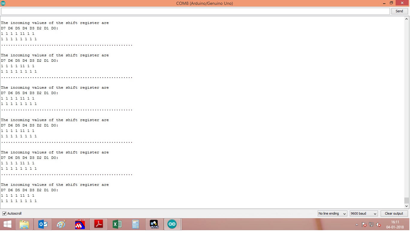
@Tom i have tested code if i am giving input as per datasheet the Serial out shown in attache image
code1.jpg
/*
 * SN74HC165N_shift_reg
 *
 * Program to shift in the bit values from a SN74HC165N 8-bit
 * parallel-in/serial-out shift register.
 *
 * This sketch demonstrates reading in 16 digital states from a
 * pair of daisy-chained SN74HC165N shift registers while using
 * only 4 digital pins on the Arduino.
 *
 * You can daisy-chain these chips by connecting the serial-out
 * (Q7 pin) on one shift register to the serial-in (Ds pin) of
 * the other.
 *
 * Of course you can daisy chain as many as you like while still
 * using only 4 Arduino pins (though you would have to process
 * them 4 at a time into separate unsigned long variables).
 *
*/

/* How many shift register chips are daisy-chained.
*/
#define NUMBER_OF_SHIFT_CHIPS   1

/* Width of data (how many ext lines).
*/
#define DATA_WIDTH   NUMBER_OF_SHIFT_CHIPS * 8

/* Width of pulse to trigger the shift register to read and latch.
*/
#define PULSE_WIDTH_USEC   5

/* Optional delay between shift register reads.
*/
#define POLL_DELAY_MSEC   1

/* You will need to change the "int" to "long" If the
 * NUMBER_OF_SHIFT_CHIPS is higher than 2.
*/
#define BYTES_VAL_T unsigned int

int ploadPin        = 8;  // Connect Pin 8 to SH/!LD (shift or active low load) - Pin 1 (!PL) of 74HC165
int clockEnablePin  = 9;  // Connect Pin 9 to !CE (clock enable, active low) - Pin 15 (!CE) of 74HC165
int dataPin         = 11; // Connect Pin 11 to SER_OUT (Serial data out) - Pin 9 (Q7) of 74HC165
int clockPin        = 12; // Connect Pin 12 to CLK (the clock that times the shifting) - Pin 2 (CP) of 74HC165

BYTES_VAL_T pinValues;
BYTES_VAL_T oldPinValues;

/* This function is essentially a "shift-in" routine reading the
 * serial Data from the shift register chips and representing
 * the state of those pins in an unsigned integer (or long).
*/
BYTES_VAL_T read_shift_regs()
{
    long bitVal;
    BYTES_VAL_T bytesVal = 0;

    /* Trigger a parallel Load to latch the state of the data lines,
    */
    digitalWrite(clockEnablePin, HIGH);
    digitalWrite(ploadPin, LOW);
    delayMicroseconds(PULSE_WIDTH_USEC);
    digitalWrite(ploadPin, HIGH);
    digitalWrite(clockEnablePin, LOW);

    /* Loop to read each bit value from the serial out line
     * of the SN74HC165N.
    */
    for(int i = 0; i < DATA_WIDTH; i++)
    {
        bitVal = digitalRead(dataPin);

        /* Set the corresponding bit in bytesVal.
        */
        bytesVal |= (bitVal << ((DATA_WIDTH-1) - i));

        /* Pulse the Clock (rising edge shifts the next bit).
        */
        digitalWrite(clockPin, HIGH);
        delayMicroseconds(PULSE_WIDTH_USEC);
        digitalWrite(clockPin, LOW);
    }

    return(bytesVal);
}

/* Dump the list of zones along with their current status.
*/
void display_pin_values()
{
    Serial.print("Pin States:\r\n");

    for(int i = 0; i < DATA_WIDTH; i++)
    {
        Serial.print("  Pin-");
        Serial.print(i);
        Serial.print(": ");

        if((pinValues >> i) & 1)
            Serial.print("HIGH");
        else
            Serial.print("LOW");

        Serial.print("\r\n");
    }

    Serial.print("\r\n");
}

void setup()
{
    Serial.begin(9600);

    /* Initialize our digital pins...
    */
    pinMode(ploadPin, OUTPUT);
    pinMode(clockEnablePin, OUTPUT);
    pinMode(clockPin, OUTPUT);
    pinMode(dataPin, INPUT);

    digitalWrite(clockPin, LOW);
    digitalWrite(ploadPin, HIGH);

    /* Read in and display the pin states at startup.
    */
    pinValues = read_shift_regs();
    display_pin_values();
    oldPinValues = pinValues;
}

void loop()
{
    /* Read the state of all zones.
    */
    pinValues = read_shift_regs();

    /* If there was a chage in state, display which ones changed.
    */
    if(pinValues != oldPinValues)
    {
        Serial.print("*Pin value change detected*\r\n");
        display_pin_values();
        oldPinValues = pinValues;
    }

    delay(POLL_DELAY_MSEC);
}
Hi,
Yes or No, DID YOU TRY THE CODE I POSTED In POST #16?
Please post JUST that codes output.
Tom...
Yes i have tested the code . Its not working. It wont genrate clock pulse. I have pasted Serial output in code1.jpg.