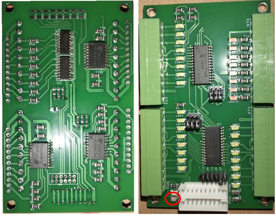
Could be the case! It was my own design. There was just one 100nF decoupling cap for two MCP ICs. Optocouplers and ULN Darlington arrays were directly on the other side of the PCB (under MCPs).
You might be right, but I want to give it try with Shift Registers. One of reasons is also max. cable length. I2C is very limited, but ShiftIn and ShiftOut should work just fine with few meters of cable.
Second reason is to release I2C bus for other onboard devices, to reduce capacitance.
Third also important is price, MCPs cost is terrible these days. I know PCF8575 are much cheaper... But Shift Register are even cheaper.
HC logic wiil not drive a cable, You will need some kind of bus drivers.
Fruitful discussion for my project, thank you all!
So here is more data for you guys.
CPU is ESP32, and I know its I2C is very weak in compare to Arduino.
I2C pull-ups are 2.2kOhms atm, tried no pull-ups, 10k, 4,7K, and 1,3K, or even disconnect OLED screen. Basically there was not change, still the same MCP goes off.
See attached picture of control box. Original layout left, current state right. Original setup had relay coil control wires from ULN2803 side by side crossing and touching with AC cables. MCPs were very unstable, when I moved my finger to about one inch distance from MCP IC, it restarted it self. At least software re-init needed to restore IO read/write functionality. Also I noticed MCS are failing after the contactor switched. Some times when I initiated MCP output switch from source code, random or all MCPs pint went high. Very unstable behavior...
I did place connection between 5VDC and 24VDC negative terminal and AC grounding terminal. After that measure I can touch IC with my finger without failing. But still it got stuck after some time or after contactor switching (contactor 230VAC coil goes on or off .. controlled by external device). After some time = when I was not there, but contactor was switching from time to time ![]()
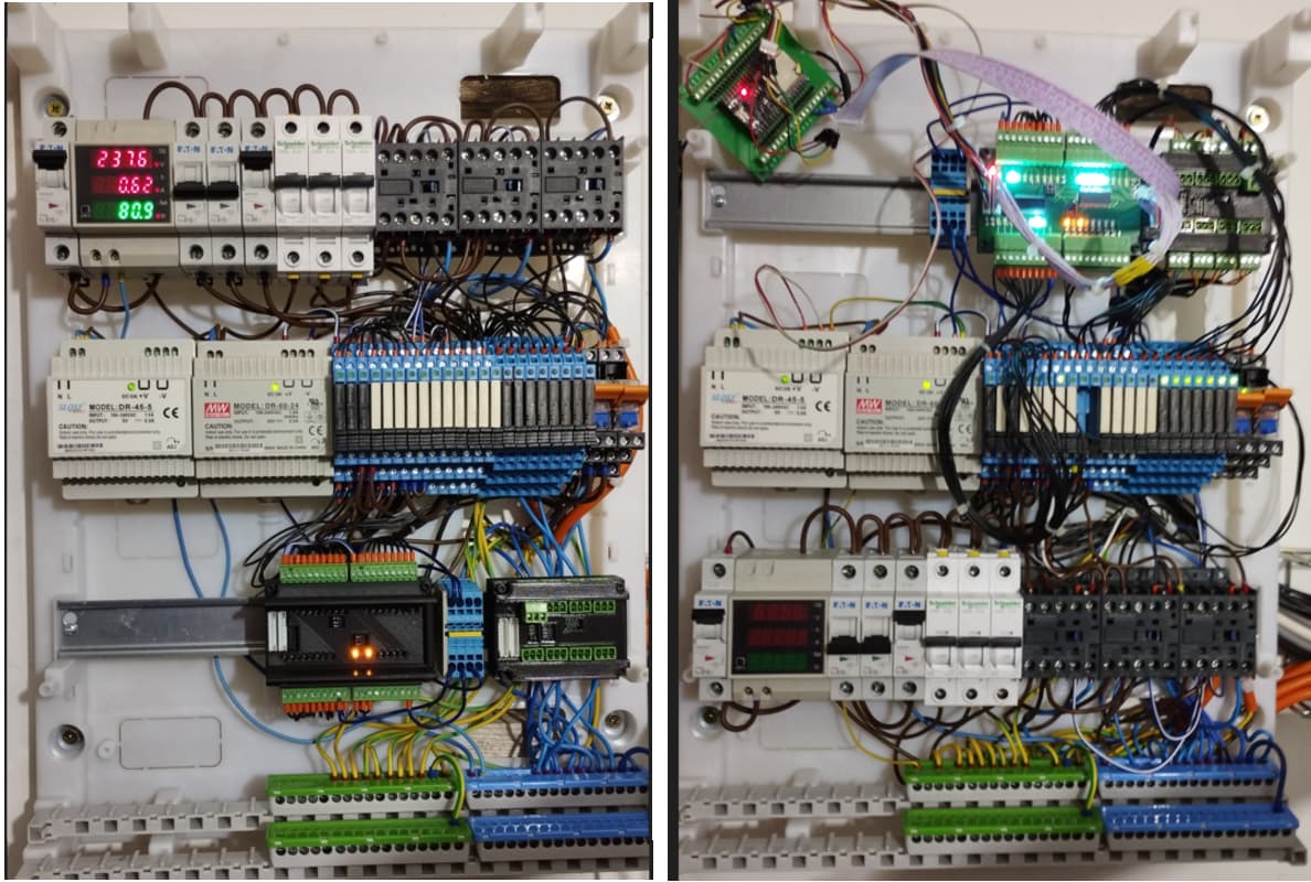
Then I changed layout of control box. Current layout is much more optimized, there is not any excessive AC cable, cables are neat, and there is not any AC cable close to PCBs. I also added Surge Suppressor add-on on contactors.

and I know relay coil control cables connected to ULN2803 are not neat yet.
But this is last improvement step I can do, add ferrite core beads and make signal cables neat, not excess. Logic voltage cables as well of coarse.
Ferrite cores arrived today, so I will try it over weekend. I will also disconnect OLED screen, only device which could obstruct I2C bus.
See PCB photos, decoupling capacitor is only one 100nF for both ICs, optocouplers are PS2801-4. On photo is board without external pull-ups, but I am currently using other board with external pull-ups (one of measures was to try other board, other MCPs, external pull-ups).
Current functionality is:
Luckily second MCP used as output only (2x ULN2803) is working and my central heating system is going. But first MCP used as 8/8 I/O (1xULN2803 and 2xPS2801-4) is every day going off the operation, software restart does not work and has to be power cycled to get back again.
I can provide source code of MCPs handling, but it is very simple. I have two independent millis timers, one for OLED screen print, and one for MCP input state update.
I do not expect wire polishing, ferrite cores will solve the problem. That's why I currently consider something different, something more reliable. And shift registers seems to be cheaper and at least different option to current situation + I2C bus will be no obstructed by frequent IO communication over cables... I2C will stay available for onboard devices.
The only limitation is number of control pins I have, so the question was "if common CLOCK pin for both ICs arrays (74HC595 & 74HC165) will be OK?" Thanks to contribution from @hiibrarahmad I believe it will be just fine. Shift registers fit my design better than I2C I/O.
But If someone has solution how to make MCPs rock stable, it would be also appreciated ![]()
I'd be putting 0.1 uf ceramic caps directly at each MCP. No foolin', you've got ground problems on that board, and caps might not solve it. When you switch large currents, with poor grounding your whole board goes 'for a ride'. Do you have access to an oscilloscope?
Unfortunately scope is not available:( gotta buy some cheap.
Will definitely try caps as you suggest,there is nothing to loose ![]()
Why grounding problems? What should I improve on next board beside decoupling caps?
Ground plane would be my approach. If not that, then thicken up your ground traces, and try to layout the board so that the MCP devices ground path to your power connection does not route past the ULN2003 ground path(I can't tell from your images, I'd need to look at both layers in a PCB layout package to really assess ground quality). I.e. any switching current for the outputs doesn't travel down the same trace as the ground return of the MCP23017. Then, start to consider ground paths between boards and supplies - do you have a rock solid ground connection between the I2C master, and the 23017s? Because any ground noise there translates into noise in the I2C signal. It's all a what if, of course, because hunting for transients is always a challenge, but that's where I'd start.
Thanks a lot for detail description of grounding issues, I home most of it understood.
Considering all recommendations we talked about are implemented in my design, would you consider MCP more reliable to Shift Registers?
OK, shift registers clocking and data lines might suffer by EMI interference, but most likely good in next cycle, in comparison to "smarter" MCP which hangs with no way back forever...
Shift Registers seems to be my way for now, or you have better suggestion?
For me, I'd try to solve any design problem with your MCP arrangement first, because what if you make a similar mistake with the Shift Register, and it's no better? What then? If you are time-pressed, bang out the shift register design, then while waiting for boards, continue to try and improve the MCP.
I'm having no problems with my MCP implementation, but then I'm in my basement, not an industrial environment. It's just that I've seen implementations of other equipment fail on grounding problems, but chalk the problem up to the 'coder', or the 'micro', without ever fixing the grounding issue.
If you want to, you can improve your board ground by simply adding copper - a tinned 14ga wire on the bottom of the board, routed to avoid shorting things out, or insulated appropriately, might make a huge difference, and if it doesn't you have more evidence that the MCP is the issue.
Oh, by the way, you are respecting the electrical specs on Page 3? In particular, although there are pin maxima for current, note the overall device maximum isn't the sum of the pin maxima. 16 pins pushing 25 ma each is 400 ma, well in excess of the device maximum of 125 ma...
just in case. (You'll run into this same issue with shift registers, if you push them to the max, though to a lesser extent as they're 8-bit devices).
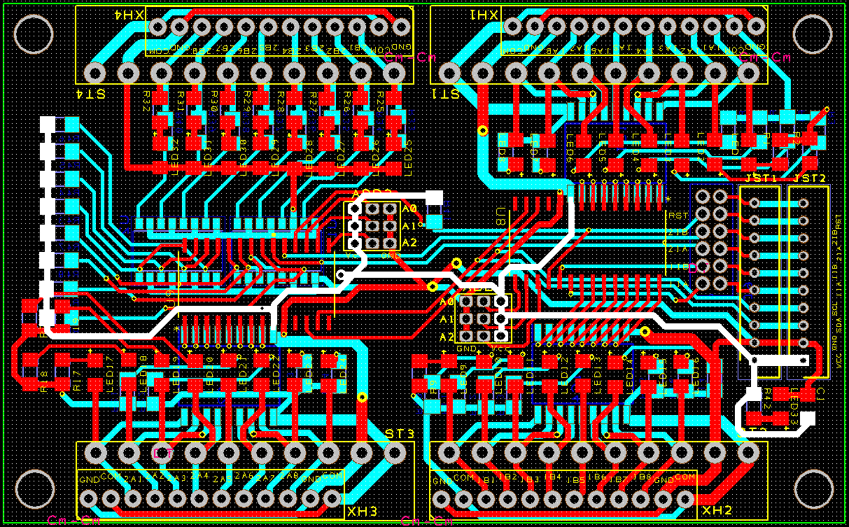
Here is ground trace, circle MCP pins cross is supply terminal.

and power trace:
How I could push failing MCP to its limits? Optocoupler pull-ups are 4.7k and ULN gate is logic level not that power hungry, or?
Yeah, after your suggestions, I was thinking about 0.1uF and extra wire hack to existing PCB meanwhile new one come.
My understanding of grounding... for new design, for example with shift registers, each IC 0.1uF, power in board 1uF, ground trace to all shift registers as short and as bold as possible. Ground for ULN or optocoupler pullups will be longer and not that bold as the main one. Pay for extra copper thickness.... Buy Simatic and go over Profinet ![]() well stop, I like C%
well stop, I like C%
Its true that second MCP, the failing one is more far from connection terminal, longer ground... CAT5 wire should do the job ![]()
Probably okay on the currents involved - remember, I've not seen a schematic posted (did you?). But that ground trace routing, and width, is not cool. The capacitor at the corner of the board is doing nothing to suppress anything near the MCP, nor is it helping to hold up the MCP 5V rail when the MCP switches current. General design rule is 0.1 uF ceramic(they're faster) as close as is reasonably possible to the power pins of any significant logic switching device. As for the board, at that level of complexity I'd probably have dropped 10uF at the 5V/Gnd connection input, as well, since the path to the power supply is long.
For a second opinion, here's another take on decoupling caps for logic, among other things:
Grumpy Mike's
There's a lot of work to make that board the way I think it should be done, so you do what you want. I just see every reason to think the MCP is the symptom, not the disease. They may, in fact, be more noise sensitive; but they haven't a hope of proving they are or aren't, in that setup.
Ya, I get the Simatic comment, but. There's a lot of hidden design history in the whole PLC world; sometimes, the big guys set their prices high for no good reason, and sometimes it's because they've got a stable of good engineers to feed. The user often can't tell which it is, so suspects greed.
I worked in R&D for a while. Time and again, I saw guys saying "we can't afford to buy that, we'll build it on the cheap, it'll be okay, trust me.", then bury hundreds of hours of debugging time and redesign costs under the rug, or in the slush of some other project; sometimes, the next year's budget included buying the hardware that should have been bought to start with.
An old truism comes to mind: "There's never time to do it right, but there's always time to do it over." And over...
You can drive a string of 595 shift registers with a single pin.
Timing becomes more sensitive; I imagine the final circuit operates VERY similarly to the now-common NeoPixel LEDs.
Regardless if you use shift registers or MCP23017s, here's another read:
grounds
See post number 3 in that thread.
Sure thing!
Shift registers can be more reliable than I2C MCP antennas in noisy environments because they use a different method of transferring data. Shift registers transfer data in parallel, which means that each bit of data is transferred on a separate data line at the same time. This makes the data less likely to be affected by noise because each bit of data is transferred independently and does not rely on a clock signal to synchronize the data transfer.
In contrast, I2C MCP antennas transfer data in a serial manner, which means that each bit of data is transmitted one at a time over a single data line. A clock signal is used to synchronize the transfer of data. This method of data transfer makes the data more susceptible to noise because any interference with the clock signal or data line can corrupt the data being transmitted.
So, if you are operating in a noisy environment, using shift registers can provide more reliable data transfer because they are less susceptible to noise. However, it's important to keep in mind that both shift registers and I2C MCP antennas can be affected by noise, so additional measures may need to be taken to ensure reliable communication in such environments.
OK, that's it, I'm burning my 74HC165/74HC595 datasheets tomorrow.
1 Like
That's good, @dougp . Best post today.
@hiibrarahmad Where, oh where, did you pull that from?
1 Like
This is false on several counts.
Most fundamentally, the whole point of a 595 is that it is a SERIAL INPUT shift register, that allows you to use fewer AVR pins for more output pins by transferring the data serially.


True, but the '165 does capture 8 bits at a time as input. Maybe this was what the OP was referring to. It's common knowledge, and I'm sure you know, noise immunity has some but not mostly a lot to do with logic types. Since the noise is environmental, it has far more to do with conductor layout, component placement, and protection and isolation circuits for the I/O. I'm skeptical about this difference which might actually reflect a difference of boards.
1 Like