Hi,
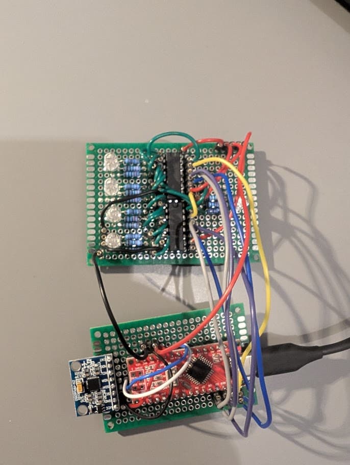
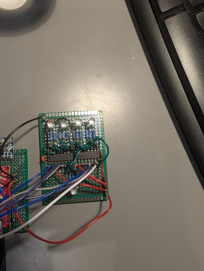
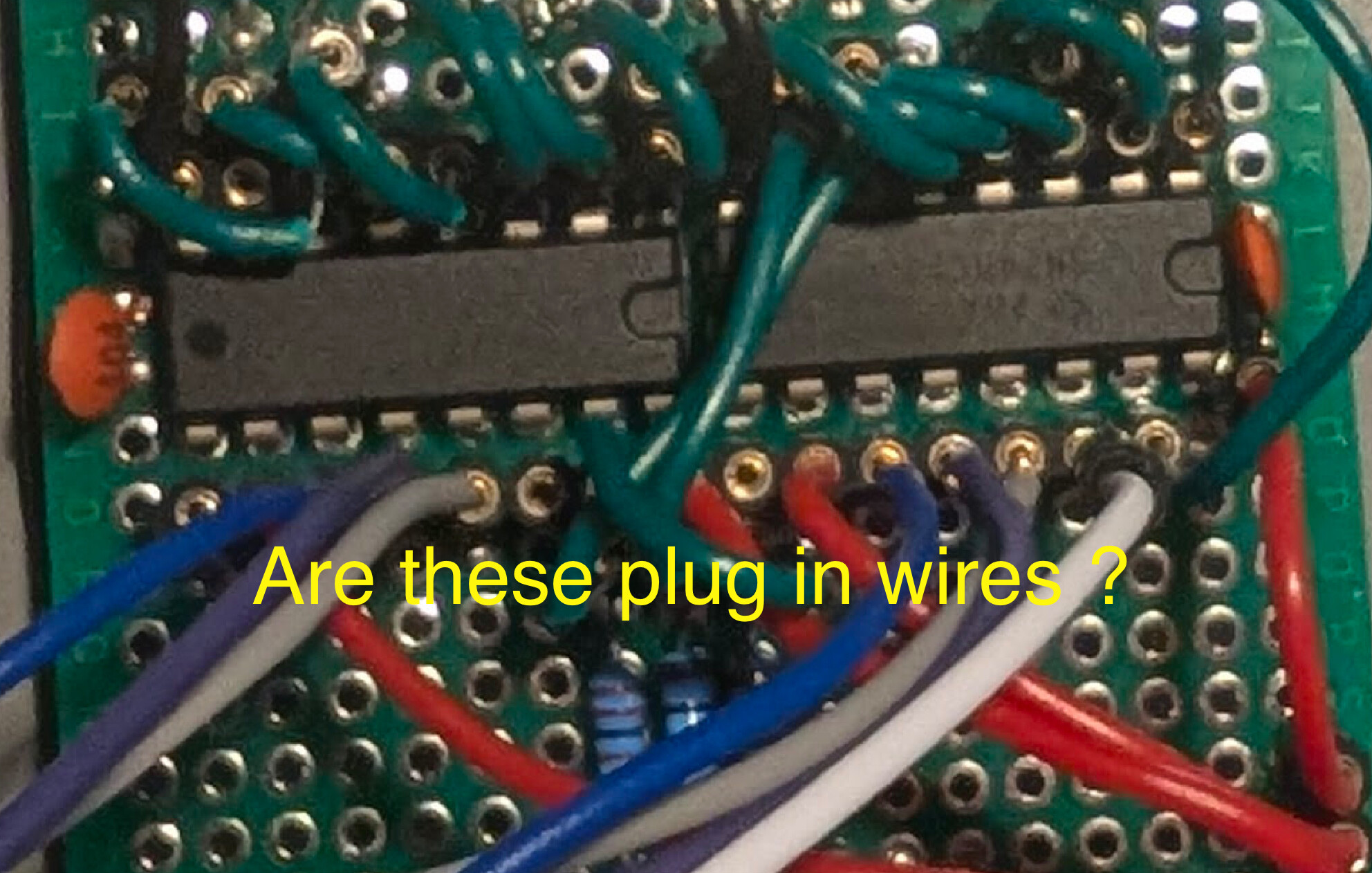
I am trying to control 5 RGB LEDs using two 74hc595 shift registers. I tried this on Wokwi and on a breadboard before finally soldering the layout. No with the soldered version I just don't get it working properly anymore.
The two LEDs controlled by the shift register that is directly connected with the data pin of the Arduino are correctly lit up in red. However the outputs of the second shift register are all high no matter what. Now I thought maybe I was unlucky and somehow damaged the second shift register during soldering. So I switched the order of the two shift registers and the I was able to control the second one, but the outputs of the first one are all set to high.
What am I missing here? I double-checked that everything is connected properly. And also switched the little solid core wire that connects the two registers with a jumper cable, to check if maybe the wire is damaged. But I can't find any reason for the behavior that is happening.
First off, your register I.C.s each need a 100nF ceramic de-coupling capacitor from their Vcc pins to the GND pins.
As close as possible to these pins.
Hi @LarryD thanks for your reply! Oh, I didn't know about the de-coupling capacitor. I will check how I could include those and then come back to let you know if it changed the outcome
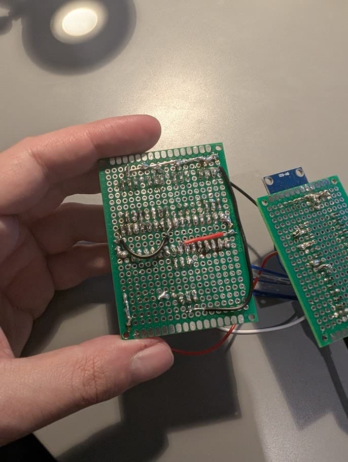
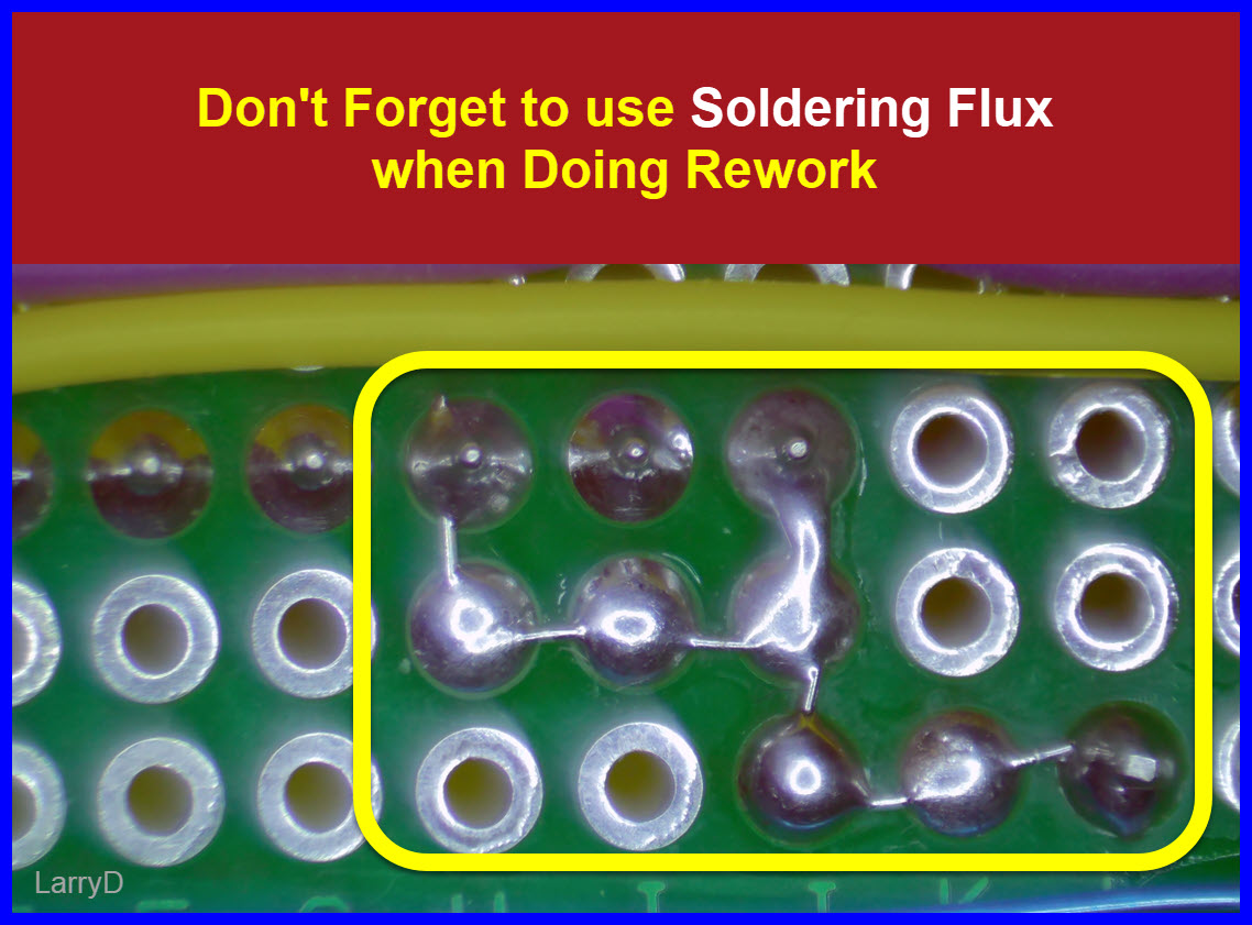
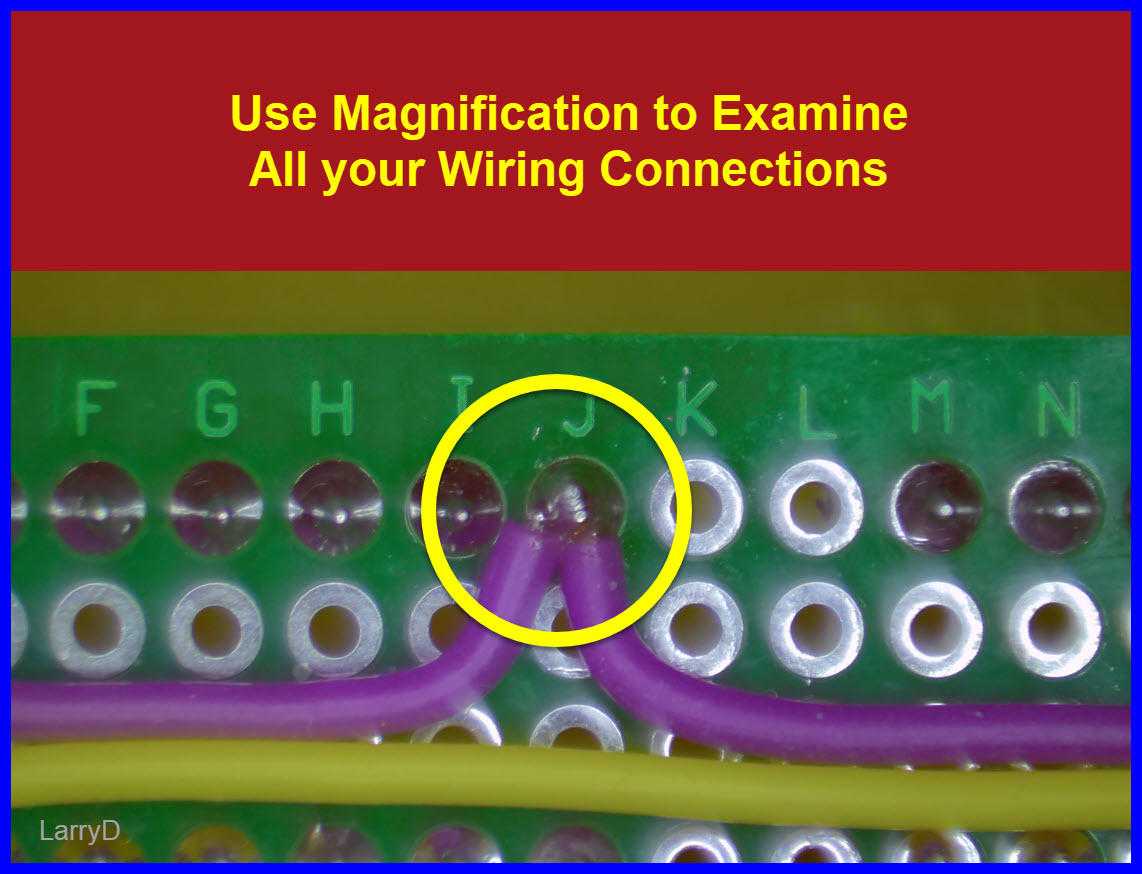
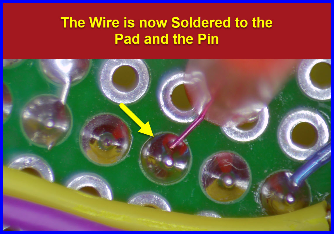
Not only that it's correct but also look for solder bridges - inadvertent connections between adjacent pins - use a magnifying glass. If using stranded wire check also for any 'whiskers' making contact with adjacent pins/devices.
I'd probably set the latch pin LOW, then do the two shiftOut operations, then set the latch HIGH. But maybe just pulsing the latch at the end, as you are doing, works with a 595 shift register.
That inverting the order of the shift registers appears to transfer the problem to the other side seems to imply that the wiring is correct.
Hacked your code in the Wokwi, run this as it introduces the issue, cycling every 5 seconds...
Although I'm a little puzzeled as to why you have 3 white leds, as you can only drive 2 and 2bits from 1 register.
My little joke
It's to introduce the "kiss of death" to the setup, by shorting the second register data input to HIGH. Reproducing what is wrong with your perf board soldering. And no you wouldn't put that in your code.
Ah, okay. So I guess using these solder brides to connect neighboring pins is not really the way to go I think I have all the parts to try the whole thing again. To place these small (30 AWG?) bare wires, I probably need to buy proper tweezers. Thanks for all the good information. That tips thread is pure gold!
I've been following this but not been able to help as I've not spotted anything that would cause a problem. However, one thing to note is I never solder ICs directly into prototype board, I solder a socket into the board then plug the IC into the socket. Doing so makes them a lot easier to replace if needed.







 I think I have all the parts to try the whole thing again. To place these small (30 AWG?) bare wires, I probably need to buy proper tweezers. Thanks for all the good information. That tips thread is pure gold!