Hi
I'm working on a project, prototype everything on a breadboard and after testing soldered everything on protoboard.
I used the Texas Instruments 74HC595 chip in my prototype, I wanted to have everything on a PCB so I built schematic and ordered PCB with SMD assembly from JLCPCB.
I chose 74HC595A by Shenzen Electronics as I thought the shift register is the same as I used in my testing.
Now I got the PCB and couldn't figure out why my leds are not working, tried to measured the voltage that the shift registers output and got very small voltage (less then 1 volt I think).
My leds cathode were connected to teensy ground and their anode to the shift register outputs.
I tried to connect the cathode of the leds to the shift register output (and the anode to Teensy VCC) and the leds are working (as expected) when the 74HC595 is set to Digital LOW.
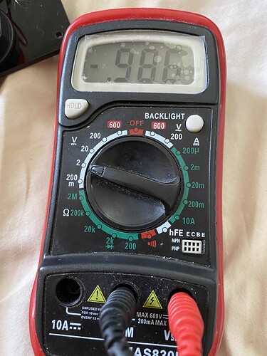
When trying the measure the voltage when the shift register is set to HIGH I got almost 1v (picture attached).
I tried to understand from the schematic via google translate (it's in Chinese), the text at the first paragraph says at the bottom of it : With 8 bus drive outputs, the data output mode is low level and high impedance state.
So what does it mean exactly ? I cannot get high voltage (>3v) in order to drive a led?
If I know that I would make sure 10 times that I'm choosing the TI 74HC595 for the SMD assembly.
74HC595A Data Sheet Link
Schema is attached (I daisy chained the shift registers, but all connected the same way).
Code:
int latchPin = 16;    // Latch pin of 74HC595 is connected to Digital pin 5
int clockPin = 17;   // Clock pin of 74HC595 is connected to Digital pin 6
int dataPin = 15;    // Data pin of 74HC595 is connected to Digital pin 4

byte leds = 0;    // Variable to hold the pattern of which LEDs are currently turned on or off

/*
 * setup() - this function runs once when you turn your Arduino on
 * We initialize the serial connection with the computer
 */
void setup()
{
  // Set all the pins of 74HC595 as OUTPUT
  pinMode(latchPin, OUTPUT);
  pinMode(dataPin, OUTPUT);
  pinMode(clockPin, OUTPUT);
}

/*
 * loop() - this function runs over and over again
 */
void loop()
{
  leds = 0; // Initially turns all the LEDs off, by giving the variable 'leds' the value 0
  updateShiftRegister();
  delay(500);
  for (int i = 0; i < 8; i++) // Turn all the LEDs ON one by one.
  {
    bitSet(leds, i);    // Set the bit that controls that LED in the variable 'leds'
    updateShiftRegister();
    delay(500);
  }
}

/*
 * updateShiftRegister() - This function sets the latchPin to low, then calls the Arduino function 'shiftOut' to shift out contents of variable 'leds' in the shift register before putting the 'latchPin' high again.
 */
void updateShiftRegister()
{
   digitalWrite(latchPin, LOW);
   shiftOut(dataPin, clockPin, MSBFIRST, leds);
   digitalWrite(latchPin, HIGH);
}


