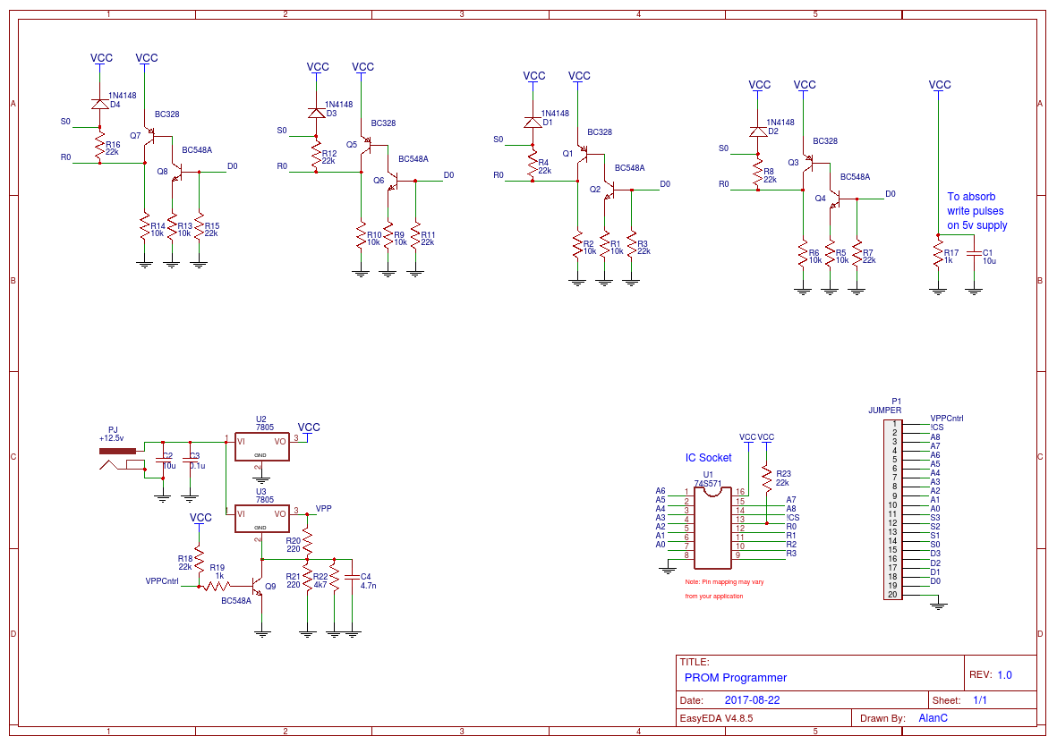
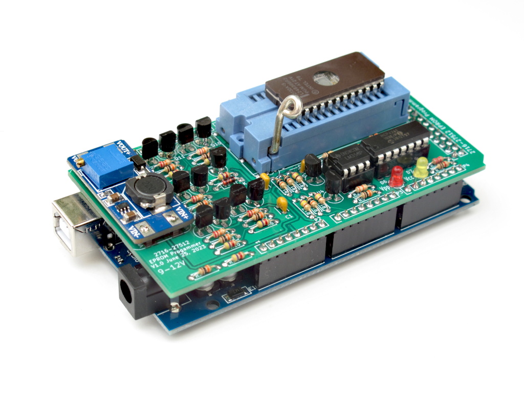
74S288 / 82S123 PROM Programmer Project

Hi all

So, I feel i am way in over my head here but i am going to give it a try anyway. I want to create a 74S288 / 82S123 PROM programmer as i have a few arcade boards and nothing which can write these PROMS.

I have seen this can be done: Click for project

Only issue is, I am a complete newbie to all this stuff. I have a technical background but nothing to do with this yet.

I just got myself an Arduino with some extras

I've also purchased most of the components needed for the board.

Is anyone able to help me better understand all this? I know I'm jumping in the deep end but i only really learn when theres an actual end goal which i need.

Thank you

Can You extract code, schematics and datasheet links and post them here?

// PROM Programmer:
//   This code programs the LOW nibble of "ROM" data to the 74S571 PROM.
//   The "ROM" data is in the source code.
//   A factory PROM is all LOWs and the Programmer writes HIGHs on bit at a time.
//   The programmer has pull up resistors on VPP and /CS for safety.
//   After the PROM has been programmed the LED will blink slowly if successful (1s on/1s off).
//   If if unsuccessful the the LED will blink quickly (0.1s on/0.1s off).
//
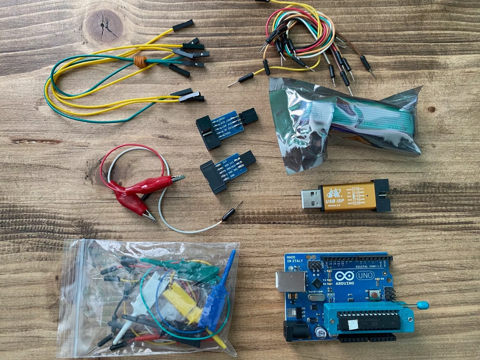
//   Programmer connections:
//     D0  <-> TX
//     D1  <-> RX
//     D2  <-> PROM A0
//     D3  <-> PROM A1
//     D4  <-> PROM A2
//     D5  <-> PROM A3
//     D6  <-> PROM A4
//     D7  <-> PROM A5
//     D8  <-> PROM D0
//     D9  <-> PROM D1
//     D10 <-> PROM D2
//     D11 <-> PROM D3
//     D12 <-> PROM A6
//     D13 <-> D13 (LED)
//     A0  <-> PROM Sense D0
//     A1  <-> PROM Sense D1
//     A2  <-> PROM Sense D2
//     A3  <-> PROM Sense D3
//     A4  <-> PROM VPP (MUST STAY HIGH FOR 5V)
//     A5  <-> PROM /CS (ACTIVE LOW)
//     A6  <-> A6 (NANO ONLY - ANALOG READ ONLY)
//     A7  <-> A7 (NANO ONLY - ANALOG READ ONLY)
// Set bytes (nibbles) to read
const int bytes=128;
#include <avr/pgmspace.h>
// Here is the "ROM" data (only the low nibble is used)
const byte PROGMEM ROM[bytes] = {
  0XDD, 0XFF, 0X8D, 0X9D, 0XDD, 0X00, 0X7D, 0X8D,
  0X9D, 0XA7, 0XB8, 0XC9, 0X2A, 0X3B, 0X4C, 0X0A,
  0X1B, 0X00, 0X1C, 0X00, 0XDD, 0XFF, 0X1D, 0XDD,
  0X0F, 0XED, 0XDD, 0X0A, 0X5D, 0XDD, 0XF9, 0X0D,
  0XDD, 0XFF, 0X1D, 0X1D, 0X00, 0XDD, 0X20, 0XED,
  0X05, 0X50, 0X00, 0XDD, 0X1D, 0XED, 0X07, 0X12,
  0X11, 0X51, 0X02, 0X11, 0X05, 0X71, 0XA7, 0X08,
  0X13, 0X11, 0X51, 0X03, 0X11, 0X05, 0X81, 0XB8,
  0X09, 0X14, 0X11, 0X51, 0X04, 0X11, 0X05, 0X91,
  0XC9, 0XDD, 0X09, 0XFD, 0X21, 0X00, 0X00, 0X00,
  0X00, 0X00, 0X00, 0X00, 0X00, 0X00, 0X00, 0X00,
  0X00, 0X00, 0X00, 0X00, 0X00, 0X00, 0X00, 0X00,
  0X00, 0X00, 0X00, 0X00, 0X00, 0X00, 0X00, 0X00,
  0X00, 0X00, 0X00, 0X00, 0X00, 0X00, 0X00, 0X00,
  0X00, 0X00, 0X00, 0X00, 0X00, 0X00, 0X00, 0X00,
  0X00, 0X00, 0X00, 0X00, 0X00, 0X00, 0X00, 0X00
};
void ReadPROM(byte bytes)
{
  byte Data;
  byte Addr;
  // Make sure controls are set for read
  PORTC|= B00010000; // Set VPP HIGH
  PORTC&= B11010000; // Set /CS LOW and D0-3 LOW
  for (Addr=0;Addr<bytes;Addr++) {
    // Set Address
    PORTD=(PORTD&B00000011)|(Addr<<2);
    PORTB=(PORTB&B11101111)|((Addr>>2)&B00010000);
    delayMicroseconds(5); // Wait for data to settle (>3 us)
    // Read the PROM
    Data=PINC&B00001111;
    if (Addr%16==0) {
      Serial.println();
      if (Addr==0) {
        Serial.print("00:");
      } else { 
        Serial.print(Addr,HEX);
        Serial.print(":");
      }  
    }
    Serial.print(" ");
    Serial.print(Data,HEX);
    delay(5); // enough time for 4 characters per loop
  }
  // Make sure controls are set to off
  PORTC|= B00110000; // Set VPP HIGH (5V) and /CS HIGH (deselected)
}
void setup() {
  // INITIALISE PORTS
  // PortC XX/VSSSS
  //       XXCP3210
  //       XXSP  
  PORTC|= B00110000; // Set VPP and /CS HIGH
  DDRC &= B11110000; // Set S0-3 as inputs
  DDRC |= B00110000; // Set VPP and /CS as outputs
  // Bit   76543210
  // PortD AAAAAART
  //       543210XX
  DDRD |= B11111100; // Set A0-5 as outputs
  PORTD&= B00000011; // Set A0-5 LOW
  // PortB XXLADDDD     
  //       XXE63210 
  //       XXD
  DDRB |= B00111111; // Set LED, A6 and D3-0 as outputs
  PORTB&= B11000000; // Set LED, A6 and D3-0 LOW
  // Set Serial
  Serial.begin(9600);
}
int  Delay=1000;
void loop() {
  byte CPort;
  byte Data;
  byte Addr;
  byte Nibble=0;
  byte BitNo;
  byte Pass;
  byte Verify;
  char Ans;
  
  delay(100);
  Serial.println("Welcome to the 74S571 PROM Programmer.");
  delay(100);
  Serial.println("Please power up the PROM Programmer now.");
  
  delay(100);                                  // Wait for output buffer to clear
  Serial.print("First read the PROM (y/n)?");  // Message
  while (Serial.available()) Serial.read();    // Flush input buffer
  while (!Serial.available());                 // Wait for response
  Ans=Serial.read();                           // Get answer
  if ((Ans=='y')||(Ans=='Y')) {
    // Read PROM
    ReadPROM(bytes);
    delay(100);
    Serial.println();
    Serial.println("PROM read done.");
  } else {
    delay(100);
    Serial.println();
    Serial.println("PROM read aborted.");
  }
  
  // PROM Programmer
  delay(100);
  Serial.println();
  Serial.print("Ready to program the PROM (y/n)?");
  while (Serial.available()) Serial.read();
  while (!Serial.available());
  Ans=Serial.read();
  if ((Ans=='y')||(Ans=='Y')) {
    delay(100);
    Serial.println();
    Serial.print("Write high or low nimble of ROM data (h/l)?");
    while (Serial.available()) Serial.read();
    while (!Serial.available());
    Ans=Serial.read();
    if ((Ans=='H')||(Ans=='h')) Nibble=4;
         
    // Make sure controls are set off (VPP and /CS HIGH)
    PORTC|=B00110000;
    for (Addr=0;Addr<bytes;Addr++) {
      // Read the data to be programmed
      Data=pgm_read_byte(ROM+Addr);
      PORTD=(PORTD&B00000011)|(Addr<<2);
      PORTB=(PORTB&B11101111)|((Addr>>2)&B00010000);
      delayMicroseconds(1);
       
      for (BitNo=Nibble;BitNo<Nibble+4;BitNo++) {
        if (((Data>>BitNo)&B00000001)==1) {
          
          // Set Data bit
          PORTB=(PORTB&B11110000)|(B00000001<<(BitNo-Nibble));
          delayMicroseconds(1);
          // Write bit cycle
          for (Verify=0;Verify<2;Verify++) {
            // Write the bit
            for (Pass=0;Pass<10;Pass++) {
              PORTC&=B11101111;      // Bring up VPP to 10.5v (active low)
              delayMicroseconds(1);
              PORTC&=B11011111;      // Select chip (active low)
              delayMicroseconds(10);
              PORTC|=B00100000;      // Unselect chip
              PORTC|=B00010000;      // Bring down VPP to 5v
              delayMicroseconds(33); // Maximum duty cycle is 25%
            }
            // Verify
            PORTB&=B11110000;        // Set D0-3 LOW (off)
            PORTC&=B11011111;        // Make /CS low (select)
            delayMicroseconds(5);    // Wait for data to settle
            // Read the PROM
            CPort=PINC;
            if ((Data&(B00000001<<BitNo+Nibble))==(CPort&(B00000001<<BitNo+Nibble))) break;
          }
      
          // Post verify bit write
          PORTB=(PORTB&B11110000)|(B00000001<<(BitNo-Nibble));
          delayMicroseconds(1);
          for (Pass=0;Pass<5;Pass++) {
            PORTC&=B11101111;      // Bring up VPP to 10.5v (active low)
            delayMicroseconds(1);
            PORTC&=B11011111;      // Select chip (active low)
            delayMicroseconds(10);
            PORTC|=B00100000;      // Unselect chip
            PORTC|=B00010000;      // Bring down VPP to 5v
            delayMicroseconds(33); // Maximum duty cycle is 25%
          }        
        }
      }
    }
    // Check Read PROM
    delay(100);
    Serial.println();
    Serial.print("Post programmed PROM read");
    ReadPROM(bytes);
    
    // Make sure controls are set to off
    PORTC|= B00110000; // VPP HIGH (5V) and /CS HIGH (deselected)
    delay(100);
    Serial.println();
    Serial.println("PROM write done.");
  } else {
    delay(100);
    Serial.println();
    Serial.print("PROM write aborted.");
  }
  delay(100);
  Serial.println();
  Serial.println("PROM Programmer done.");
  
  while(true) {
    digitalWrite(13,HIGH);
    delay(Delay);
    digitalWrite(13,LOW);
    delay(Delay);
  }
}

Some thoughts:

The project you linked to is in no way a beginner's project.

First, it is for a 512x4 bit PROM (74S571). The 74S288 is 256x8. So the Uno won't have enough I/O pins by itself to program a full byte.

(A quick look through my 1977 NatSemi Memory Databook indicates that they program in the same fashion.)

Second, the sketch is... minimal doesn't begin to describe it. It's a one off program designed to program a fixed pattern of nibbles. It's more of an example than anything else.

An experienced person with coding and hardware design experience would be able to use the schematic and code as a basis to build on to create a useful programmer. It would not however be something they'd knock out in an evening. And having made my own EPROM programmer for fun and education, I feel I speak with some experience on the subject.

And no, I'm not offering to tutor. Just pointing out that you have a lot of learning and work ahead of you.

Thanks. You've already got a good reply.

Yeah, that. Nicely complete, as far as it goes, though.

I have a lot less confidence in that "they'll all program the same" statement in the design - I remember that era as being full of chips with slightly different requirements :frowning:

The PROMs you're talking about are programmed by literally "burning" connections on the chip - little bits of wiring (silicon or metal) on the die that are given a high-current pulse to vaporize them and change the state of the bit in memory ("fuses", just like in a fuse box). This requires high voltage and high current power be applied to certain pins, with certain shapes of pulses. This "obviously" isn't reversable, so if something goes wrong, you throw away the chip.

(This is substantially different than modern programmable memories like Flash, where the current requirements are low, and any higher voltages needed are usually generated internally, and programming is reversible. However, this is where still-used terms like "fuses" and "burn", come from.)

Given that these PROMs don't seem to be made any more, and therefore sell for ridiculous prices, I'd be looking for a more modern replacement, like maybe REPROGRAMMABLE 82S123
(I didn't know that a 22v10 had that much "memory!") (Alas, GALs are relatively obsolete tech these days as well, though they're still available, and you can purchase programmers for them. I wonder if you can do the "simulate ROM" hack with something more modern like one or two of those "greenpak" PLDs.)

Thank you all yes i did think i was a bit over my head with this to say the least. I have a 1981 Cosmic Avenger arcade board which i can programme the ERPOMS for no issue but these bipolar PROMS are really hard to find a programmer for.

That said, I will still keep the Arduino and im going to learn some basics with it. I enjoy learning stuff like this so it won't go to waste. Going to this level of programming and design though i doubt it haha.

Thanks everyone

1 Like

Here's guy who has apparently done this:

https://www.youtube.com/watch?v=mj218WpNHEA

Back in the day, I built a programmer for the 40-pin 82S100 so as to get replacements for the Commodore C64's PLA chip. That turned out to be a largely manual process, and included high voltage drives.

But the 82S123 is much smaller. You have 32 bytes. Five address lines, and eight data lines. So even less fancy than in the video, you could set up DIP switches on these lines, set them manually one address at a time, and press a button to burn the data. Thirty-two bytes wouldn't take all that long.

But it should be possible to automate the process with an Arduino driving two shift registers and a transistor circuit for the high voltage (if any is needed). The first step is to find out exactly what the programming process is - the timing, the polarity, the voltage, etc., which will probably not be in the datasheet.

The downside is that these chips can't be reprogrammed. So when you need to make a change, you have to burn a new chip. And I suspect they aren't cheap. The alternative is to find an active EPROM or EEPROM part that could replace the 82S123, but which no doubt will have a completely different pinout, and make a daughterboard for it that would plug into your arcade. Then you could program the EEPROM from an Arduino. But I don't know how easy it would be to find full parallel addressed EEPROMs these days.

[82S123 bi-polar PROM replacement kit (82S123-to-27512)]
(82S123 bi-polar PROM replacement kit (82S123-to-27512))

This topic was automatically closed 180 days after the last reply. New replies are no longer allowed.