7segments with 74hc595

Good evening,

I need to control 7segment display with 74hc595 IC.

I tested the code with 7 LEDs and 74hc595 IC, it's working correctly.
I tested the 7segments directly connected to Arduino and it's working correctly.

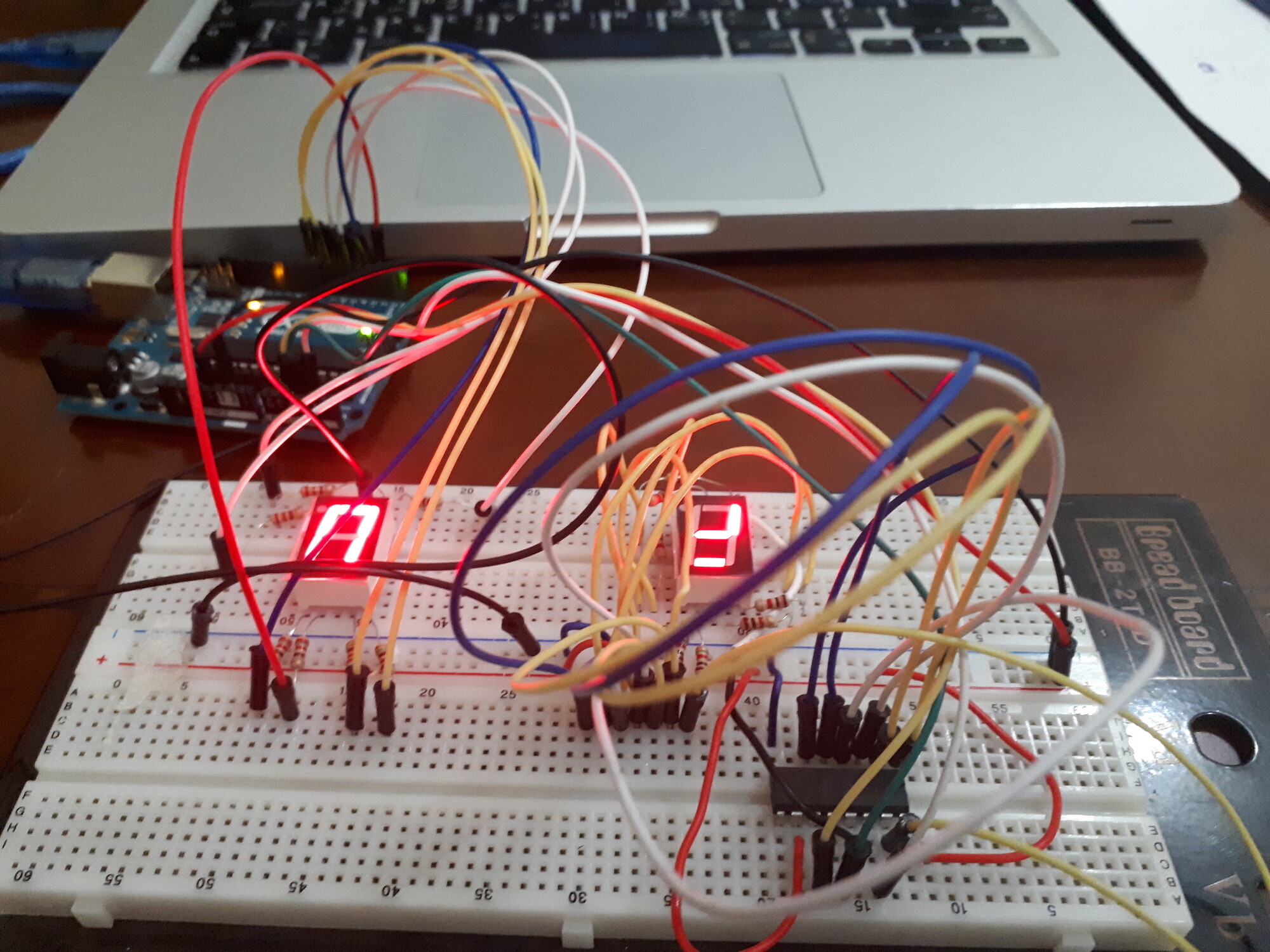
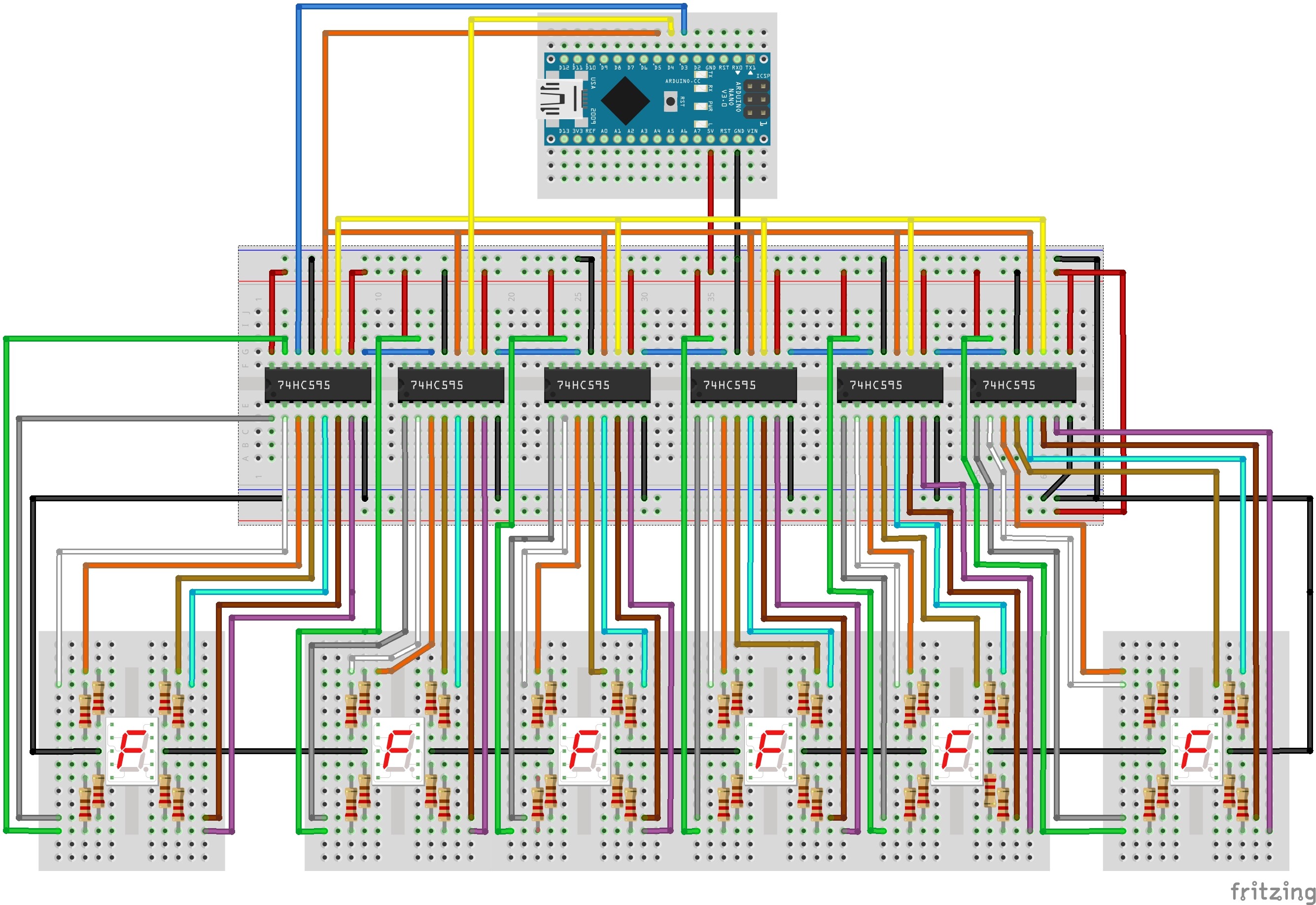
When I integrate the shift register and the the 7 segments, three segments are continuously ON regardless of the value of the shift register.

I am using 8 10k resistors for the LEDs segments,
when I checked some videos online, I saw that they are using only one resistor ?

how to proceed ?

/Pin connected to ST_CP of 74HC595


#define DS_PIN    A4 // data
#define STCP_PIN  A3 // storage register clock  //////// latch pin
#define SHCP_PIN  A2 // shift register clock ///////// clockpin 


void setup() {
  //set pins to output so you can control the shift register
  pinMode(STCP_PIN, OUTPUT);
  pinMode(SHCP_PIN, OUTPUT);
  pinMode(DS_PIN, OUTPUT);
}

void loop() {
  // count from 0 to 255 and display the number 
  // on the LEDs
  //for (int numberToDisplay = 0; numberToDisplay < 256; numberToDisplay++) {
    // take the latchPin low so 
    // the LEDs don't change while you're sending in bits:
    int numberToDisplay = 7; 
    
    digitalWrite(STCP_PIN, LOW);
    // shift out the bits:
    shiftOut(DS_PIN, SHCP_PIN, MSBFIRST, numberToDisplay);  

    //take the latch pin high so the LEDs will light up:
    digitalWrite(STCP_PIN, HIGH);
    // pause before next value:1  
    delay(1000);
  //}
}

I attached image of the circuit.

Is your end result just to display a count down on one digit? Or is there a more involved project going on here that we don't know about? I have been working on a project involving segment displays and might be able to help if I knew exactly what you were trying to end up with as a final result. The picture is hard to make out the exact schematic.

In the code, I am trying to test the connection only.

I keep changing the number to display, but the same three segments are always ON.

Later, on I want to display a value from a keypad on the seven segments.

Here is a quick test code you can run, just change which number you want to display using the byte string when you want to write to the display. I will try and get you a connection diagram when I get in front of my Arduino setup.

// define the LED digit patterns, from 0 - 9
// 1 = LED on, 0 = LED off, in this order:
//                74HC595 pin     Q0,Q1,Q2,Q3,Q4,Q5,Q6,Q7 
//                Mapping to      a,b,c,d,e,f,g of Seven-Segment LED
byte seven_seg_digit[10] =  { B11100110,
                              B11111110,
                              B11100000,
                              B10111110,
                              B10110110,
                              B01100110,
                              B11110010,
                              B11011010,
                              B01100000,
                              B11111100,
                             };
 
// connect to the ST_CP of 74HC595 (pin 3,latch pin)
int latchPin = 4;
// connect to the SH_CP of 74HC595 (pin 4, clock pin)
int clockPin = 5;
// connect to the DS of 74HC595 (pin 2)
int dataPin = 3;
 
void setup() {
  // Set latchPin, clockPin, dataPin as output
  pinMode(latchPin, OUTPUT);
  pinMode(clockPin, OUTPUT);
  pinMode(dataPin, OUTPUT);

  digitalWrite(latchPin, LOW);
  shiftOut(dataPin, clockPin, LSBFIRST, B10110110 );  //change these to the number from the array to show the digit you want
  shiftOut(dataPin, clockPin, LSBFIRST, B11111100);  
  digitalWrite(latchPin, HIGH);
}
 void loop(){}

I tried the code, but I got the same result.
Only segments a,g, and e are ON
I tried two combination numbers.

xxxWALDOxxx:
Here is a quick test code you can run, just change which number you want to display using the byte string when you want to write to the display. I will try and get you a connection diagram when I get in front of my Arduino setup.

// define the LED digit patterns, from 0 - 9

// 1 = LED on, 0 = LED off, in this order:
//                74HC595 pin    Q0,Q1,Q2,Q3,Q4,Q5,Q6,Q7
//                Mapping to      a,b,c,d,e,f,g of Seven-Segment LED
byte seven_seg_digit[10] =  { B11100110,
                              B11111110,
                              B11100000,
                              B10111110,
                              B10110110,
                              B01100110,
                              B11110010,
                              B11011010,
                              B01100000,
                              B11111100,
                            };

// connect to the ST_CP of 74HC595 (pin 3,latch pin)
int latchPin = 4;
// connect to the SH_CP of 74HC595 (pin 4, clock pin)
int clockPin = 5;
// connect to the DS of 74HC595 (pin 2)
int dataPin = 3;

void setup() {
  // Set latchPin, clockPin, dataPin as output
  pinMode(latchPin, OUTPUT);
  pinMode(clockPin, OUTPUT);
  pinMode(dataPin, OUTPUT);

digitalWrite(latchPin, LOW);
  shiftOut(dataPin, clockPin, LSBFIRST, B10110110 );  //change these to the number from the array to show the digit you want
  shiftOut(dataPin, clockPin, LSBFIRST, B11111100); 
  digitalWrite(latchPin, HIGH);
}
void loop(){}

Schematic

Here is a link for the schematic I posted on another thread I am working on right now. Keep in mind this schematic will differ from your model segment display, but the pin connection to the shift register should be the same. This is shifting out to multiple displays, but the only difference is the Q7 on the 1st register goes to the Data Pin on the second which you won't need. Hope this helps.

If you get the same result on both your code and Waldo's code, then you probably have the wiring wrong somewhere. It's not possible to tell much from your picture.

But as for the resistors, I see a lot of people connecting LEDs and 7-segment displays without resistors, and it may work, but in most cases it's just wrong. If you are displaying all seven or eight segments at the same time, then you need individual resistors on the segment lines so that all the segments that are turned on will be equally bright whether you are displaying "8" or "1". There are legitimate ways to avoid this, such as multiplexing by segment instead of by digit, but for what you are doing with the 595, I think you should continue to use your resistors.