7x7 "analog" clock on flip dot matrix

Hello,

I'm trying to achieve a working clock on 7x7 flip dot matrix. My problem is until now I was only using it to show icons which I generated in program called : LED Matrix Studio (http://maximumoctopus.com/electronics/builder.htm)

What i want to get is a piece of code that would translate time (hour and minutes in hh:mm format) into a matrix in this format: 0x00, 0x08, 0x18, 0x00, 0x00, 0x04, 0x00 (5:15 in the example)

My visual idea is shown in the picture below:

Can anybody show me in the right direction in search for the right knowladge? I'm sure this has been tuted milions of times, but I even don't know what to search for:( Is multiplexing the thing to master?
Thanks

And the flip dot matrix itself to show you what do i work with:

Hi, can you post one of the sketches you have working with your icons? Use code tags so it looks like this

Paul

One big issue here is that you are trying to make a clock.
How do you intend to keep track of the time? What I mean is, how will the Arduino "know" what time it is?

As for the icons, I figure that at most you will need 144 icons. (12 icons per hour for 12 hours) But that's a lot if icons, so I can see why you are trying to make things easier for yourself. Notice that I said "at most 144 icons": there are tricks you can do to greatly reduce this number, but I don't want to get into that just yet.

I suggest that you begin by making a clock that shows minutes only (not hours). That way, you will need only 12 icons to start with.

Once you have the minutes part done, then it would be a good time to take care of the hours.

Odo is right, you will need an RTC module or something to give the Arduino the time. Otherwise you will have to re-set time time somehow each time the Arduino is powered up or reset, and even then it will not be very accurate. The other options are to get the time from the internet or from a radio time signal, but those are not suitable for beginners. I recommend a ds3231 rtc module.

In terms of icons, we won't know for sure until we see some example code for your display, but i was not imagining using any icons. I imagined a couple of small arrays holding the positions of the hour and minute indicators.

PaulRB:
Odo is right, you will need an RTC module or something to give the Arduino the time. Otherwise you will have to re-set time time somehow each time the Arduino is powered up or reset, and even then it will not be very accurate.

If you're just making a demo and don't need it to be particularly accurate, then you don't need an RTC.

If you actually want to use this as a real clock, then you will want an RTC.
By the way, it might be a good idea to have an option for a "digital" display mode, such as this one:

07:08:19           12:34:56           23:59:59
                                                
....... 0          @...... 1          @@..... 2
@@@@@@@ 7          .....@@ 2          ....@@@ 3
......@ 0 1        @@@.... 3          @@@@@@@ 5 2
@@@@@@@   +7       ...@@@@ 4          @@@@@@@   +7
....... :          ....... :          ....... :
@....@@ 1 2        @@@@@.. 5          @@@@@@@ 5 2
@@@@@@@   +7       .@@@@@@ 6          @@@@@@@   +7

Hello,

PaulRB - the problem with my code that works with the flip dot screen is that it's protocol is not open and so by posting the full code here I would brake the copywrites. This is why I changed the code below a bit:

// Where you see PROTOCOL - this means that I use the flipdot protocol that is copywritghts protected

#include <SoftwareSerial.h>

SoftwareSerial mySerial(10, 11); // RX, TX

byte send_data_buffer [] = { PROTOCOL, 0x00, 0x00, 0x00, 0x00, 0x00, 0x00, 0x00, PROTOCOL };
          byte ikona1 [] = { PROTOCOL, 0x08, 0x1C, 0x3E, 0x7F, 0x22, 0x22, 0x22, PROTOCOL };
          byte ikona2 [] = { PROTOCOL, 0x3F, 0x21, 0x61, 0x41, 0x41, 0x41, 0x7F, PROTOCOL };
          byte ikona3 [] = { PROTOCOL, 0x1C, 0x63, 0x00, 0x36, 0x00, 0x22, 0x1C, PROTOCOL };
          byte kotek  [] = { PROTOCOL, 0x00, 0x04, 0x46, 0x7F, 0x78, 0x48, 0x00, PROTOCOL };

void setup() {
mySerial.begin(9600);
//while (!Serial);
}

void loop() {
  for (int x=0;x<11;x++) mySerial.write(kotek[x]);
  delay(15000);
  for (int x=0;x<11;x++) mySerial.write(ikona1[x]);
  delay(15000);
  for (int x=0;x<11;x++) mySerial.write(ikona2[x]);
  delay(15000);
  for (int x=0;x<11;x++) mySerial.write(ikona3[x]);
  delay(15000);
  for (int x=0;x<11;x++) mySerial.write(send_data_buffer[x]);
  delay(15000);
}

The RTC issue. This program is running on Yun and one of the main uses for this board would be internet connection (blynk app), so I figured out that I could just grab the time from the internet via some API. Didn't research this but I'm just sure, there are easy ways to ask for accurate time, and than to parse it from some json being send at me.

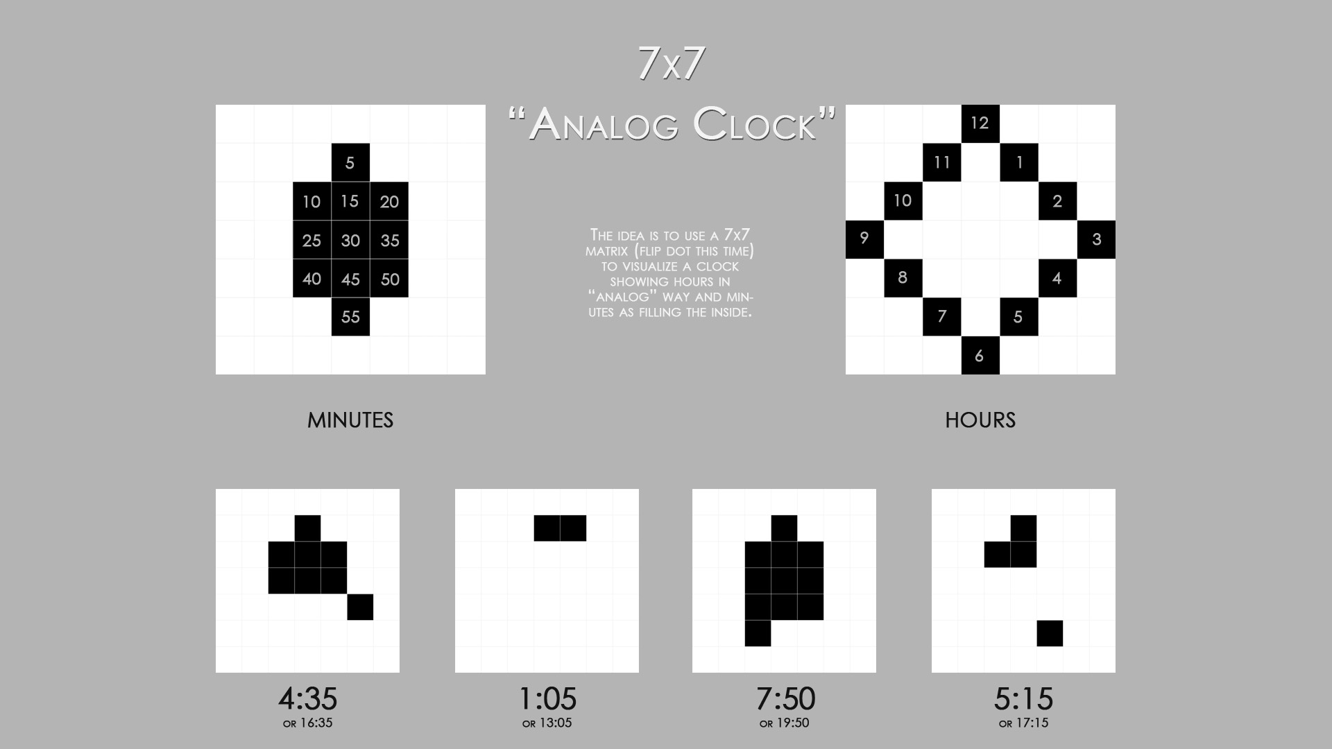
The idea to make a clock with minutes only. Good idea, this will make ma go through the whole logic, before the problem with adding arrays will occure.

odometer - the clock that you've shown is a bit clock of some kind, true?

I just checked the "time" issue.

There is a pretty nice way to get this on Arduino Yun:

Basicaly:
"This example for the Arduino Yún gets the time from the Linux processor via Bridge, then parses out hours, minutes and seconds for the Arduino's 32U4. The Yún must be connected to a network to get the correct time."

ethelder:
Hello,

PaulRB - the problem with my code that works with the flip dot screen is that it's protocol is not open and so by posting the full code here I would brake the copywrites. This is why I changed the code below a bit:

// Where you see PROTOCOL - this means that I use the flipdot protocol that is copywritghts protected

....

I don't understand how four bytes is enough to violate copyright law, but I am not a lawyer, so I will just have to take your word for it that it is enough to violate the law. (That's all it is is four bytes, right?)

Well, anyway... If I were you, I would use only seven bytes for each icon, not eleven; and I would write a function to take care of the PROTOCOL so that I don't have to repeat the PROTOCOL for each icon. Something like:

const int ICON_SIZE = 7;

void drawIcon(byte* icon) {
  Serial.write(PROTOCOL); // copyrighted mumbo-jumbo
  // next, we take care of the icon itself
  for (int i=0; i<ICON_SIZE; i++) {
    Serial.write(icon[i]);
  }
  Serial.write(PROTOCOL); // more mumbo-jumbo
}

and then to actually draw an icon, you could use something like:

byte myDiagonal[] = {0x01, 0x02, 0x04, 0x08, 0x10, 0x20, 0x40};
drawIcon(myDiagonal);

Warning: I have no means of testing any of this code, and it might have serious bugs, so use it at your own risk.

Looks very straight forward. Certainly no need to learn about multiplexing or anything.

I will try to post some code fragments later to show how i would approach drawing the clock symbols. In short, i would set up a few arrays showing the byte and bit positions for each of the hour indicators 0(=12) to 11, and the minute indicators 5, 10, 15... 50, 55. Then i would write a few lines of code using bitSet(). Easy.

Hello

PaulRB - I understand that you suggest using one set of arrays for minutes, one set for hours and than "adding" those two arrays? One person suggested this solution to me, but I didn't have the possibility to wrap my head around it. You've written that you will post some code. That would be very kind of you. Very helpful. Don't bother to make the whole clock for me, just if you could show me the piece with "bitwise or" on two arrays looking like this one:

byte myDiagonal[] = {0x01, 0x02, 0x04, 0x08, 0x10, 0x20, 0x40};

since i understand this is what you suggest : Bitwise operation - Wikipedia

I will also post the finished code of my clock when I have it:)

odometer - this is not just four bytes, the part I've send you is the true information, the rest of the array consists of address etc. It's not my idea - the protocol is being "protected" by the producer of the flip dot, and I just respect that. Thanks for the idea, to send the protocol sensitive data in a separate function - this is good idea in terms of memory handling and it makes the code cleaner - good idea, will do it.

ethelder:
odometer - this is not just four bytes, the part I've send you is the true information, the rest of the array consists of address etc. It's not my idea - the protocol is being "protected" by the producer of the flip dot, and I just respect that.

I can't check this for you, but it does compile...

// Where you see PROTOCOL - this means that I use the flipdot protocol that is copywritghts protected

#include <SoftwareSerial.h>
#define PROTOCOL 01,02

SoftwareSerial mySerial(10, 11); // RX, TX

const byte hourByte[] = {3,4,5,6,7,8,9,8,7,6,5,4};
const byte hourBit[]  = {3,2,1,0,1,2,3,4,5,6,5,4};
const byte minByte[]  = {4,5,5,5,6,6,6,7,7,7,8};
const byte minBit[]   = {3,4,3,2,4,3,2,4,3,2,3};

void setup() {
mySerial.begin(9600);
//while (!Serial);
}

void loop() {
  //loop over hours 12(=0) to 11
  for (int h=0;h<12;h++) {
    // loop over minutes in 5 min steps
    for (int m=0;m<60;m+=5) {
      // Set up blank data buffer
      byte send_data_buffer[] = { PROTOCOL, 0x00, 0x00, 0x00, 0x00, 0x00, 0x00, 0x00, PROTOCOL };
      // Set hour bit
      bitSet(send_data_buffer[hourByte[h]], hourBit[h]);
      // Set minute bits
      for (int n=0; n<m/5; n++) bitSet(send_data_buffer[minByte[n]], minBit[n]);
      // Send to display
      for (int x=0;x<11;x++) mySerial.write(send_data_buffer[x]);
      delay(1000);
    }
  }
}