I am going to be building an 8x8x8 LED cube for my HSC project for electronics. I was wondering if anyone would have any hints or important information i may need to build this.
Also which would be better, having anode columns or cathode columns?
connect up cathodes in columns, use P-channel MOSFETs to source current to anode layers.
8 TCIP6B595 can both sink current for the cathodes, and a 9th to pull the MOSFET gates low to turn on one layer at a time. Will need 64 x 20mA per layer, 1.28A 5V, 2A supply will be great.
I have boards, can provide bare or as a kit.
Gonna be on the road a lot this week, might be a little slow sending things out.
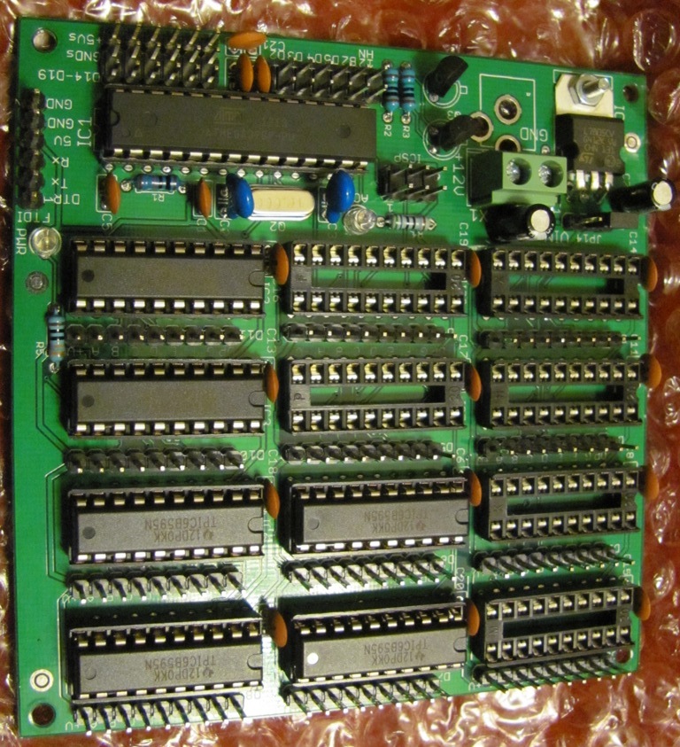
So what you do is get a PCB like this http://www.dipmicro.com/store/PCB-UNI30H
and build up the LED cube on that with the 64 current limit resistors, 8 P-channel Logic Level Low Rds MOSFETs and their resistors, headers to bring in the cathode signals from the other board, and +5/Gnd.
I have a feeling if I go through with this you will be saving my ass again crossroads.
I have no idea about any of the component you have mention as i was looking at this particular setup:
Sorry I was on my phone before so the image didn't come up.
Yours seems to be slightly different to the website i linked. Which do you think is easier as I have extremely little knowledge of the shift registry stuff?
"With this setup, we only need 64 (for the anodes) + 8 (for each layer) IO ports to control the LED cube."
where the columns are driven high, and a layer pulled low to enable it.
While mine pulls the columns low, and drives the layers High to enable it.
My idea is to use 9 shift registers, one to enable the selected layer and the other 8 to control the columns,
vs a demux chip and 8 shift registers.
With my idea, SPI is used to blast out the 9 bytes, and a really high refresh rate can be achieved. 9 bytes at 8 MHz SPI rate will take about 9uS to send out. For a 30 Hz refresh rate, 33.3mS per total cube update, means each layer can be left on ~4200uS minus the 9uS byte transfer time. During that ~4.2mS you can be updating the data to be displayed next, via serial, button pushes, reading pots, etc.
It takes 512 bytes to represent the whole cube in memory; you can have 2 copies, one that is being cycled thru for displaying, one that is being updated for the next display cycle.
Or control it with a 1284P chip, 16K of SRAM, can have lots of copies that you rotate thru and can take more time to update.
I have not made a cube, too busy to solder up all the LEDs.
With 64 LEDs on at a time, drawing up to 20mA, that's 1.28A.
You can use a 500mA supply, just use larger value current limit resistors so you have under 7.8mA per LED. Even less if the 500mA is also supply the arduino and shift registers:
(5V - Vanode transistor - Vf of LED - Vcathode transistor )/(available current/64) = resistor value
LED has a voltage drop,
Cathode device will have a voltage drop,
Anode device will have a voltage drop.
With going off the instructable that i posted earlier this is what it asked for:
512x LEDs (plus some extra for making mistakes!)
64x resistors. (see separate step for ohm value)
1x or 2x large prototype PCBs. The type with copper "eyes", see image.
1x ATmega32 microcontroller (you can also use the pin-compatible ATmega16)
3x status LEDs. You choose color and size.
3x resistors for the status LEDs.
8x 74HC574 ICs
16x PN2222 transistors
16x 1k resistors
1x 74HC138 IC
1x Maxim MAX232 IC
1x 14.7456 MHz crustal
2x 22pF ceramic capacitors
16x 0.1uF ceramic capacitors
3x 1000uF electrolytic capacitor
3x 10uF electrolytic capacitor
1x 100uF electrolytic capacitors
8x 20 pin IC sockets
1x 40 pin IC socket
2x 16 pin IC socket
1x 2-pin screw terminal
1x 2wire cable with plugs
9x 8-pin terminal pins
1x 4-pin terminal pins, right angle
2x 16-pin ribbon cable connector
1x 10-pin ribbon cable connector
Ribbon cable
2x pushbuttons
2x ribbon cable plugs
9x 8-pin female header plugs
Serial cable and 4pin female pin header
Piece of wood for template and base
8x optional pull-up resistors for layers
5v power supply (see separate step for power supply)
Do you see any problems with these components as I want to get them as soon as i can
Tell you the truth, I have next to no idea what i am looking for.
I need to find a cube layout/tutorial/instructable that I can make a stand alone arduino controlled LED cube.
How do i find the V of anode transistors and cathode so i can use that equation?
They are looked up in their datasheets. You can find Vce or Vds at various current levels for transistors , and Voltage Out High or Low at the current level being used for shift registers.