A better way to control a 7-segment display?

When I search for ways to control a 4-digit 7-segment display with Arduino, I find countless threads and tutorials using a 74HC595. The worst of these use one 74HC595 per digit. The best use a single 74HC595 for all digits, plus transistors to turn individual digits on and off. But even the best eat up a lot of Arduino pins (example: Lesson 28 - 4 Digit 7 Segment Display - YouTube).

Are there any similar chips designed specifically for 4-digit 7-segment displays? Bonus points if it has built-in current limiting resistors.

Or tricks to avoid using an individual Arduino pin (with a transistor) to control each digit? Maybe diode logic to control four digits with just two pins?

There are chips like the MAX7219, designed for 8-digit 7-segment displays (often used for 8x8 matrix displays). You don't have to implement all 8 digits.

If you use the 74HC595-per-digit you have the advantage of not having to worry about flicker. You will need only three pins for as many digits as you like.

2 Likes

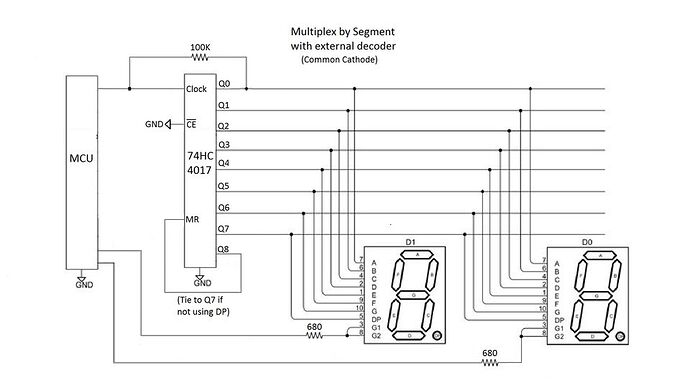
Not designed specfically for that purpose, but if you mutiplex by segment, and if you use common cathode displays, you can use the 74HC4017 to drive the segments. You would need a processor pin for each digit, plus one pin to clock the 4017. So 5 processor pins for a four-digit display. You would also need a resistor for each digit, but no transistors. See the attached pic of a two-digit display as an example. The concept is discussed in this video:

https://www.youtube.com/watch?v=8w09Zy8MQrc

1 Like

The problem with that arrangement, is that it puts illuminated segments in parallel. So "1" which has only two segments, is brighter than "8" which has 7 segments. Even segment illumination depends on current limiting per segment, not shared. So, a resistor for each segment.

1 Like

No. Even the cheap modules run all the drive lines from a 74HC595. So only 3 processor lines are required - data, clock, and SR load. Also the most popular multifunction board with 4 digit 7 segment display.

1 Like

Buy modules that have the shifting and resistors included or a display with NeoPixels or 7-segment display with I2C: https://www.adafruit.com/product/1270.

1 Like

You can drive the cc-type 4-digit 7-segment display unit (Fig-1) using SevSeg.h Library; where, there is no need of shift registers and power transistors. The 20 mA rating of the IO lines are good enough to offer optimum light emission from the LEDs of the display devices.

4digi7seg
Figure-1:

Test Sketch (untested) 4567 should appear on the display unit

#include<SevSeg.h>
SevSeg sevSeg;           //create object sevSeg

int numberToShow = 4567;

void setup()
{
  byte segDPins[] = {8, 9, 10, 11, 12, 13, 6, 7};  //DPin8 = seg-a, …, DPin-7 = seg-p
  byte ccDPins[] = {A2, A3, A4, A5};   //DPin-A2 = cc0, DPin-A2 = cc1, ...
  sevSeg.begin(COMMON_CATHODE, 4, ccDPins, segDPins, false, false, false, true);
  sevSeg.setNumber(numberToShow, 0, LOW);
}

void loop()
{
  sevSeg.refreshDisplay();  //4567 will appear on display unit.
}
1 Like

TM1637 modules are now cheaper on the market than 74HC595 modules. Don't waste your money.

2 Likes

Oh very interesting, thank you for sharing!! I worry that approach will show noticeable flickering (you can see that in the video, though probably due to the camera), but I'll consider it!

I don't think that's accurate. Since it's cycling through the LEDs one by one, there will never be more than one segment active simultaneously.

Thank you for the suggestion, but this eats up pins on the UNO, which is exactly what I want to avoid.

Usually, it isn't cycling through them one by one. I wrote code to do that, but I've never seen anyone else do that. :slight_smile: Universally, one digit is selected together with all the segment drives. All the selected segments stay on until the next digit is selected.

If you know of some code that does that, I'd like to see it. I thought I was being quite clever, but great minds think alike.

I was referring to ShermanP's example, which uses a 74HC4017 decade counter instead of the 74HC595. Interesting to hear you coded a solution to get similar results from a 74HC595 though :open_mouth:

Oh, I get it now. That would work. You would need more digit lines though, if you have more than 2 digits in the display...

1 Like

I've also stumbled on this solution, which is an interesting compromise. Two 74HC595 chips, where one controls the digit selection through transistors. Not sure I'd prefer that over some of the better chips y'all have suggested, but it does only need 3 pins.

Minus the driver transistors, that is how the modules work. Any software driven multiplexing is constrained by refresh requirements though. I use a timer interrupt.

1 Like

Actually, those are the best of all using 74HC595 since they require no multiplexing and efficiently use the limited current capability of the 74HC595.

Those using 74HC595s and digit transistors will work OK but are sharing the segment drive over all four digits, and require you to perform the multiplexing. Very clunky!

Those using two 74HC595s without transistors are simply rubbish.

All 74HC595 designs use three pins.

But if you seriously want a 4-digit display and are not just playing coding games for pure entertainment, you use a module with a MAX7219, or as mentioned a TM1637 module if it has the decimals arrangement that suits. :+1:

1 Like

Then the choice is MAX7219 as @johnwasser has suggested in Post-2. This is a SPI device and you require only 3-wires to drive an 8-digit display unit. The chip contains scanning circuit, power driver etc. See the diagram of Fig-1.


Figure-1:

Test Sketch (to show 4 5 6 7 on DP0, DP1, DP2, DP3 positions of display unit)

#include<SPI.h>
byte registerAddress[] = {0x0C, 0x09, 0x0A, 0x0B}; //control registers of MAX7219, see data sheets
byte registerData[] = {0x01, 0x00, 0x01, 0x07};
//normal modeo; no-decode;intensity;8-digit scan
byte dataArray[8];  //to hold cc-codes (no-decode format)
byte digitAddress[] = {0x01, 0x02, 0x03, 0x04, 0x05, 0x06, 0x07, 0x08};//DP0-DP7
byte lupTable[] = {0x7E, 0x30, 0x6D, 0x79, 0x33, 0x5B, 0x5F, 0x70,
                   0x7F, 0x7B, 0x77, 0x1F, 0x4E, 0x3D, 0x4F, 0x47
                  }; //0, 1, ...., E, F ; no-decode cc-code see data sheets

void setup()
{
  pinMode(10, OUTPUT);  //LOAD Pin of MAX7219
  //-------------------
  SPI.begin();
  // bitSet(SPCR, 4);              //UNO is Master SPI
  //  SPI.setBitOrder(MSBFIRST);    //MSB_bit will be transferred first
  SPI.setClockDivider(SPI_CLOCK_DIV128); //TX rate = 16MHz/128 = 125 kbit
  //  SPI.setDataMode(SPI_MODE1);//MOSI is sampled at the rising edge of CLK
  //------------------------------------------------
  digitalWrite(10, LOW);      //Low at LOAD pin
  //---- dataArray update-----------------------------
  dataArray[0] = lupTable[4];   //no-decode cc-code of digit-4
  dataArray[1] = lupTable[5];   //n0-decode cc-code of digit-5
  dataArray[2] = lupTable[6];   //no-decode cc-code of digit-6
  dataArray[3] = lupTable[7];   //no-decode cc-code of digit-7
  //-------------------------------------------------


  //---keep intializing the Mode of Operation------------
  for (int i = 0; i < 4; i++)
  {
    SPI.transfer(registerAddress[i]);
    SPI.transfer(registerData[i]);
    digitalWrite(10, LOW);
    digitalWrite(10, HIGH); //assert LH/LL on LOAD pin
    digitalWrite(10, LOW);
  }

  //--keep transferring the result/data----------------------
  for (int i = 0; i < 4; i++)
  {
    SPI.transfer(digitAddress[i]); //DPX position
    SPI.transfer(dataArray[i]);   //shows 4 5 6 7 on display
    digitalWrite(10, LOW);
    digitalWrite(10, HIGH);       //assert LH/LL on LOAD pin
    digitalWrite(10, LOW);
  }
}

void loop()
{

}
1 Like

No, the same current always flows through each segment no matter how many digits are lighting up that segment. The resistor on the common collector sets the current since only one segment is selected at a time.

I don't see any flickering in the video. In any case, there was no flickering when viewed live. In any case, you can always refresh more frequently if you like. Notice that the refresh rate does not depend on the number of digits since it's the segments that are multiplexed. But the refresh rate will be faster than multiplexing by digit because each segment is on only 1/7 of the time rather than 1/4 of the time.

This method is supported by the sevseg.h library, but I don't think that includes the 4017 part. But the Github repo associated with the video has 4017 code that doesn't use a library.

The other consideration is that since no transistors are used, the 4017 has to be able to supply enough current to drive four segments at a time, as determined by the common collector resistors. This is more likely to work if your seven segment displays are super efficient, as discussed in the video.

If parts count and pin usage are important, I think you'll find that this method is about as good as it gets.

1 Like

Which you can chain endlessly to have even more digits

Hi,
Google

max7219 4 digit 7 segment

There are many examples and sellers with ready made modules.

Tom... :smiley: :+1: :coffee: :australia: