Controlling 10-pin 2-digit 7-segment Display with shift register.

Hi folks

I'm pretty new to Arduino and this is my first post. :slight_smile:

I would like to control a 10-pin 2-digit 7-segment Display (cathode) with a shift register.

I'm fine with controlling a 1-digit display, and I can control either side of the 2-digit display (by switching common cathodes), but I just can't figure out how to print separate numbers to each segment.

How is this accomplished when you can only send the display 1 byte?

Thanks

The technique is called Multiplexing.

It relies on "persistence of vision" to fool the eye that both digits are lit, when in fact only one is lit at any instant.

To do this, the best way it to use a dedicated chip like max7219 or ht16k33. You can do it with arduino pins and shift register but the results will never be quite as good.

What type of shift register do you have?

In order to do it with a shift register, you need to connect the common cathode pins to 2 more Arduino pins. But this can overload the pins with too much current and damage them. To avoid damage, you can use higher series resistors, making the display less bright, or you can use a couple of npn transistors to take the load off the arduino pins.

I tried to script something that would turn one segment off while the other is on and vice versa, but it didn't work. But maybe it was just my code. I guess I'm on the right track then.

I'll look into multiplexing - thanks.

flyagaricus:
turn one segment off while the other is on

That can work, but lighting one segment at a time will make the display very dim. Better to light one whole digit while the other is off.

flyagaricus:
it didn't work.

Here's a tip: never say that on this forum. It drives everyone crazy! Say what actually did happen and what you expected or wanted to happen. For example "I wanted the 2 digits to show 3 and 4 but actually the same 6 segments of both digits lighted but some were brighter than others".

PaulRB:
That can work, but lighting one segment at a time will make the display very dim. Better to light one whole digit while the other is off. Here's a tip: never say that on this forum. It drives everyone crazy! Say what actually did happen and what you expected or wanted to happen.

Fair enough!

So, I was able to achieve some results by shifting each digit separately to it's respective segment while turning the other off and adding a 15 ms delay between shifts, however, there is a noticeable flicker on both segments.

I assume this is what you meant by 'results will never be quite as good.'?

Flicker means that you have not got the code right to give each digit the same amount of time, every time - something in the code is causing erratic delays. This is one reason you must not use the "delay()" function or "while".

Alternating digits (not segments) at 15 ms should be reasonably adequate - 33 cycles per second, although two or three times as fast would be better.

"the results will never be quite as good" may be a reference to the time it takes to load eight bits into a shift register, but using the right timing code that is not too much of a problem. You really need a latched shift register such as a 74HC595 and should not be using obsolete devices such as 4000 or 74LS series.

Even so, the current driving capability of the 74HC devices is limited and once you have played with multiplexing purely for the practice, if you want to build something serious you need to use an IC designed to do it properly such as the MAX7819. In case you were not aware, complete display modules using this are - or used to be before "Covid" - readily available on eBay.

(Curiously, eBay appears to be partially "down" for the last 24 hours or so! :astonished: )

I think you intended MAX7219. $2 at TaydaElectronics last time I checked. Also get a 10K resistor, a 0.1uF cap, and a 10uF cap.

Howdy, I'm stumped and have a question like the original post in this thread. I've succeeded in working with a 2-digit 7-segment display (10 pin. stats here: http://www.xlitx.com/datasheet/CL3621AH.pdf ) The circuit and code are shown below to hopefully help someone in their journey.

Now, here's my thing. I intend to make a clock which shows Hours: Minutes: Seconds. Three blocks of 2-digit 7-segment displays. Obviously I need to chain latch shift registers like 74HC595, right? I'm familiar with that from other binary LED projects (through-hole LEDs, not components like this one.) Not familiar with the MAX2719 (7219?). But, sticking with the 74HC595 for now, I arrive at two questions:
(1) Do I really need 2 shift registers for this component? One per digit?
(2) I cannot figure out how to wire up two 74HC595s to this 10-pin component; any advice?

/*
    CL3621AH 2-digit 7-segment display
    http://www.xlitx.com/datasheet/CL3621AH.pdf

    ******* COMMON CATHODE **********

    connect ardruino pins 10, 11 to resistors (330 ohm) and
    then to component pins 5, 10. The rest connect direct.

    compenent      arduino uno
   ---pins-------------pins---
    5        dig.1          10
    10       dig.2          11
    __________________________
    3          A             2
    9          B             3
    8          C             4
    6          D             5
    7          E             6
    4          F             7
    1          G             8
    2          DP            9
   ____________________________

      Component pins (1 - 10)

      (10)     (9)     (8)     (7)     (6)
        |       |       |       |       |
  *******************************************
  *                                         *
         A A A A             A A A A
        F        B          F        B
        F        B          F        B
        F        B          F        B
         G G G G             G G G G
        E        C          E        C
        E        C          E        C
        E        C          E        C
         D D D D   DP        D D D D   DP
  *                                         *
  *                                         *
  *******************************************
       |       |       |       |       |
      (1)     (2)     (3)     (4)     (5)


   array digit[] values represent LED on/off switches

   0b[G][F][E][D][C][B][A]

  0b0111111, // Zero
  0b0000110, // One
  0b1011011, // Two
  0b1001111, // Three
  0b1100110, // Four
  0b1101101, // Five
  0b1111101, // Six
  0b0000111, // Seven
  0b1111111, // Eight
  0b1100111  // Nine

  ***************************************************
  This code just cycles through 00-59.
  ***************************************************

*/

// these values turn segments on/off to display
// representations of numbers Zero through Nine.
int digit[] =
{
  0b0111111, // Zero
  0b0000110, // One
  0b1011011, // Two
  0b1001111, // Three
  0b1100110, // Four
  0b1101101, // Five
  0b1111101, // Six
  0b0000111, // Seven
  0b1111111, // Eight
  0b1100111  // Nine
};

// declare digit 1; digit 2
int d1, d2;

void setup()
{
  for (int i = 2; i < 12; i++)
  { // we are using arduino pins 2-11
    pinMode(i, OUTPUT);
  }
}

void loop() {
  for (int j = 0; j <= 59; j++)
  { // first loop: 0-59 with some binary conversions
    d2 = j / 10; 
    d1 = j % 10; 

    setBrightness(10, 25);
    digitalWrite(10, LOW);  // LOW = active
    digitalWrite(11, HIGH); // HIGH = inactive
    shiz(d1);                // ones digit
    delay(10);

    setBrightness(11, 25);
    digitalWrite(10, HIGH); // HIGH = inactive
    digitalWrite(11, LOW);  // LOW = active
    shiz(d2);                // tens digit
    delay(10);
  }
}

void shiz(int n) {
  for (int i = 2; i < 9; i++)
  {
    digitalWrite(i, bitRead(digit[n], i - 2));
  }
}
void setBrightness(int p, int v) {
  // p = pin; v = value
  // common cathode, so high is low, flip the value
  v = 255 - v;
  analogWrite(p, v);

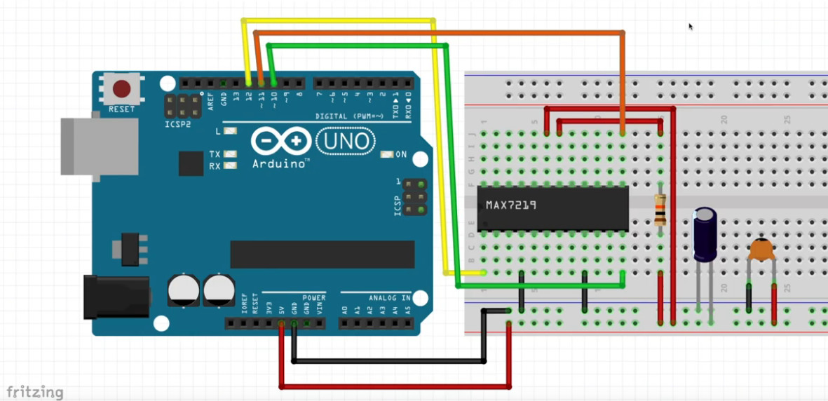
The following image represents my confusion. :slight_smile:

Your images are not visible. Please read the forum guide in the sticky post at the top of the forum section to find out how to post images here. Using external image hosting sites is not necessary.

+1 karma for posting your code correctly.

Obviously I need to chain latch shift registers like 74HC595, right?

Not necessarily, there are many ways. Chaining would help reduce the number of Arduino pins required.

through-hole LEDs, not components like this one.

The data sheet you linked to also shows a thru-hole package. Did you post the correct link?

Do I really need 2 shift registers for this component? One per digit?

One per digit would be 6 shift registers for your 6 digits, right? But you cannot connect 1 per digit with these displays because, like nearly all such displays, they have common segment pins. You can only use one chip per display. You could use 1 or 3 shift registers to drive the segments in your circuit. More chips mean brighter displays, but it might be bright enough to be readable with only 1, if used indoors in a dim room. You could use an extra shift register to indirectly drive the digit pins, saving more Arduino pins.

I cannot figure out how to wire up two 74HC595s to this 10-pin component;

Connect the shift register outputs to the segment pins, using a series resistor for each output. For the digit pins, you may need transistors or perhaps a special version of the same shift register, tpic6c595, to avoid overloading and damaging Arduino pins.

All this sound complicated? It is, compared to using the max7219!

PaulRB:
Your images are not visible.[...]

Thank you PaulRB. I think I've fixed 'em now.

PaulRB:
The data sheet you linked to also shows a thru-hole package. Did you post the correct link?

The link is correct. My language is at fault. Previously I've chained 3 TPIC6b595 shift registers, each controlling 8 regular individual 5mm LEDs, which I called through-hole to distinguish 'em from this component (2 digit 7-segment) which I did not realize is also a through-hole. So, my bad, sorry. The component link is correct. That is the 2 digit 7-segment display I'm currently trying to use in a set of 3 (6 digits.)

One per digit would be 6 shift registers for your 6 digits, right?

The full display goal of: Hours (2 digit) Minutes (2 digit) Seconds (2 digit) will be 6 digits (3 components), yes. How many shift registers or max7219 thingies must be used is where I claim ignorance, and willingness to learn. Quick search suggests 1 MAX7219 will drive 2 digits. So, 3 Max7219, chained, should drive 6 digits using just 3 pins from Arduino. Which is a perfectly sane solution.

All this sound complicated? It is, compared to using the max7219!

Sounds like it is time for me to do some max7219 homework. Thank you for the tip!

CrossRoads:
I think you intended MAX7219. $2 at TaydaElectronics last time I checked. Also get a 10K resistor, a 0.1uF cap, and a 10uF cap.

Thank you for the TaydaElectronics tip. Great price! Max7219 on the way. Resistors and caps in hand.

cdrk:
I think I've fixed 'em now.

I see 'em now, but I don't like 'em much! :wink:

There is an error in the first circuit, if used with the code you posted. With different code, it could be ok. The problem is as follows. Your code multiplexes by digit, so one digit's required segments are on while the other digit's segments are off. But there is only one series resistor per digit. This forces the segments that are on to share current between them. If the digit being displayed is a "1", then only 2 segments share the current and look bright. If "8" is displayed, the same current is shared between 7 segments, so they look much dimmer. If your code multiplexed by segment rather than by digit, this would not be a problem, because only 1 segment from each digit would be lit at any time.

When multiplexing by digit, you need 7 or 8 series resistors, on the segment pins. But that would present another problem. Now, the segments don't share the same current, so those currents add up, and could become too much for the Arduino pin, connected to the digit pin, to deal with and become damaged. You could use higher value series resistors to avoid that, but the display would be dimmer. You could only use those series resistors if you also used transistors to take the strain off the Arduino pin.

Your max7219 circuit looks ok so far. Except for the use of an Uno with a breadboard, of course! Much better to use a larger breadboard and an Arduino that can plug into it, such as a Nano.