I keep getting the error in the title when trying to upload a sketch. I have tried to switch to different USB ports, resetting the ESP32 camera wrover, resetting the IO extension board and the UNO. I do not believe I am missing any drivers either.
The wiring is all correct according to the assembly instructions of the starter kit, so I do not think it is an issue with wiring like other similar posts.
This is the output when the sketch fails to upload, I cannot find anything on the troubleshooting site which has fixed it either.
Serial port /dev/cu.usbmodem00001
Connecting......................................

A fatal error occurred: Failed to connect to ESP32: Invalid head of packet (0x00): Possible serial noise or corruption.
For troubleshooting steps visit: https://docs.espressif.com/projects/esptool/en/latest/troubleshooting.html
Failed uploading: uploading error: exit status 2
Hi @blacknand. This error might be caused by the communication lines between the computer and the microcontroller on the board not being able to support the rather high default upload speed. If so, the problem should be fixed by reducing the upload speed, which is configurable via a convenient menu.
Select Tools > Upload Speed > 115200 from the Arduino IDE menus and then try uploading the sketch again, just as you did before. Hopefully this time the upload will be successful. If not, add a reply here on the forum thread to let us know and we'll investigate further.
Optimizing Upload Speed
If the sketch upload no longer failed after reducing the upload speed, you will have determined that the board is not capable of managing uploads at the default 921600 baud, but is capable of them at 115200 baud.
Especially with more complex sketches, the upload will take a significant amount of time at 115200 baud. It is likely that the board is capable of managing uploads at some speed higher than 115200 baud, so it is worth doing some experimentation to determine the maximum speed at which you can reliably upload to the board. You can do this by repeating the "Configure Upload Speed" procedure above, but selecting different speeds each time. Then attempting an upload to see if the new speed is appropriate.
Hi @ptillisch. Thanks for the reply. I changed the upload speed to 115200 baud and still got the same error. For reference this is the sketch I am trying to upload:
It is possible for a short or external circuitry connected to the Arduino board to interfere with the upload process, causing this type of upload error.
Make sure the board is not sitting on anything conductive that could short the contacts on the bottom of the board. Make sure there isn't any conductive debris (e.g., strands of wire or component leads) on the board or on the surface the board is sitting on.
If you have a shield or any external circuitry or components connected to your Arduino board, try this experiment:
Disconnect the USB cable of the Arduino board from your computer.
Disconnect any shields, modules, external circuitry, etc. from your board.
Connect the Arduino board to your computer with a USB cable.
Now try uploading a sketch to the board again. Does the upload succeed?
This experiment will determine whether the upload error was caused by interference from your external circuitry. If so, you can then focus your attention on identifying the specific problem with the circuit and resolving it.
You took some nice photos but it appears you have a dirty lens or screen. Do you have anything connected to pins 0 and 1, the terminal serial pins, if so remove it and try uploading again.
When I directly plug the board into my computer via USB-C, there are no LEDs at all so the board does not turn on at all. The manufacturer said they would replace this part so I think I will just have to develop the robot without the camera for the mean time.
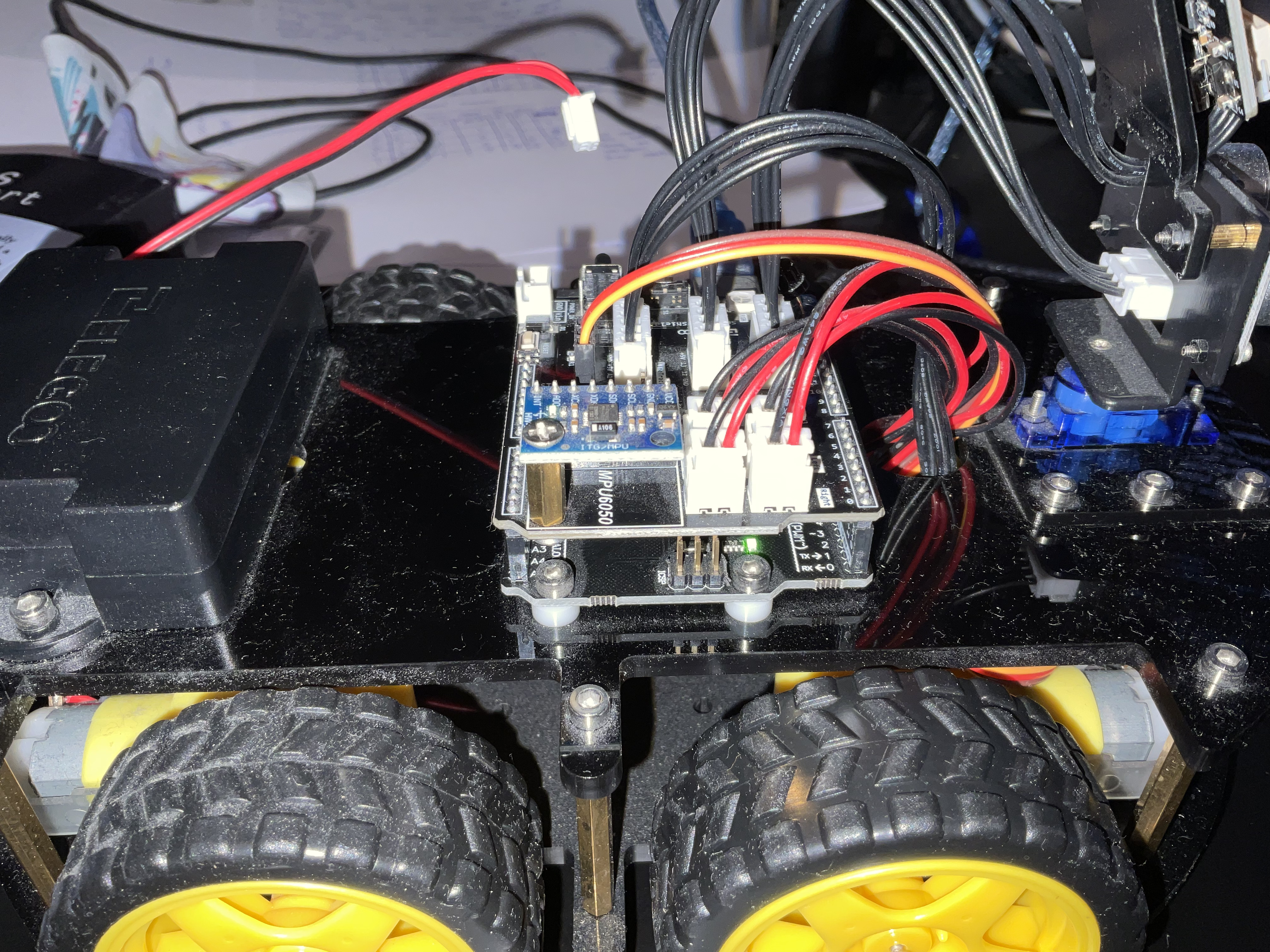
That is very odd because in post #1, we can see clearly that indeed the "ON" LED on the UNO R3 derivative board is lit when you only have it connected to the computer:
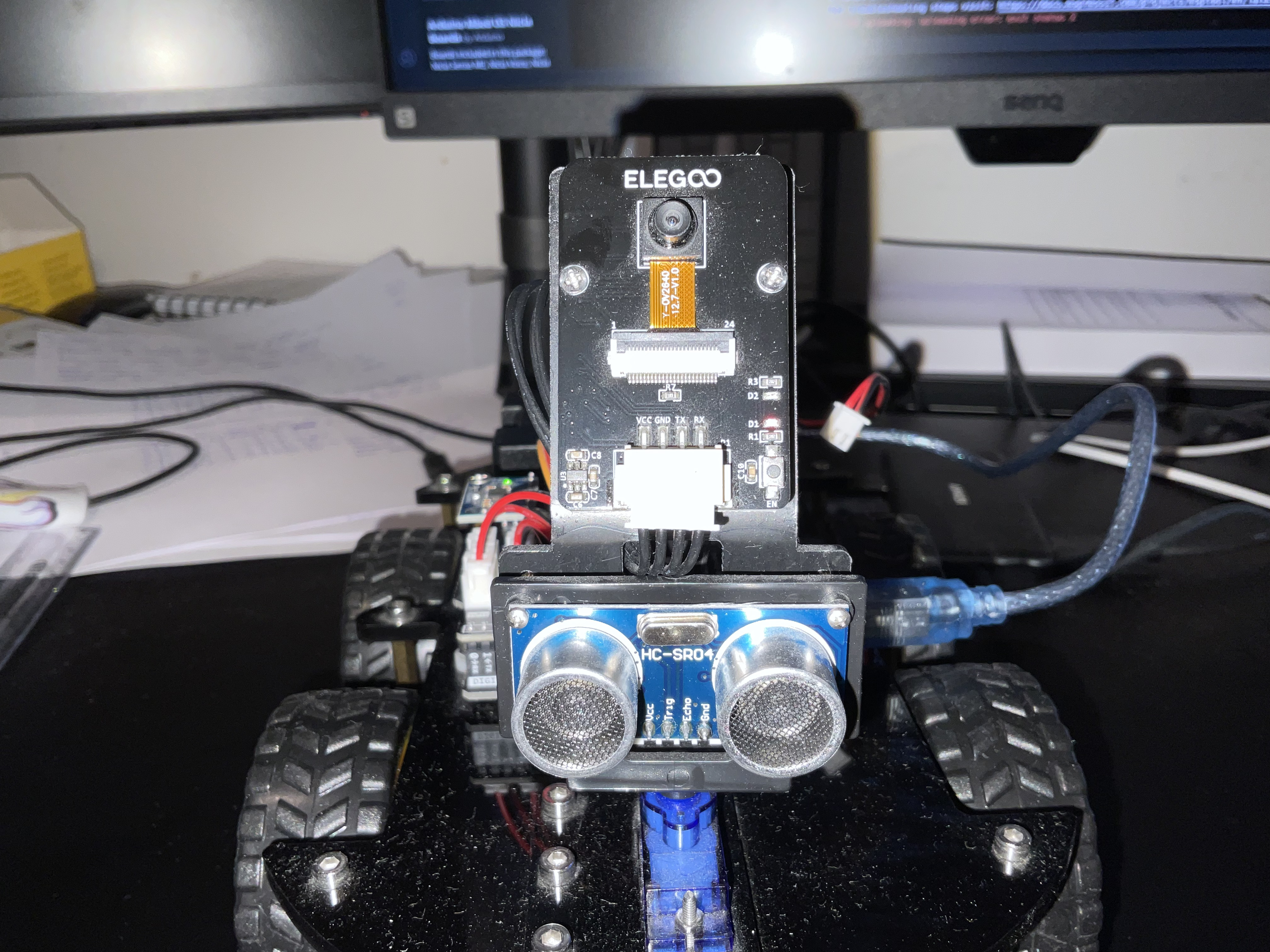
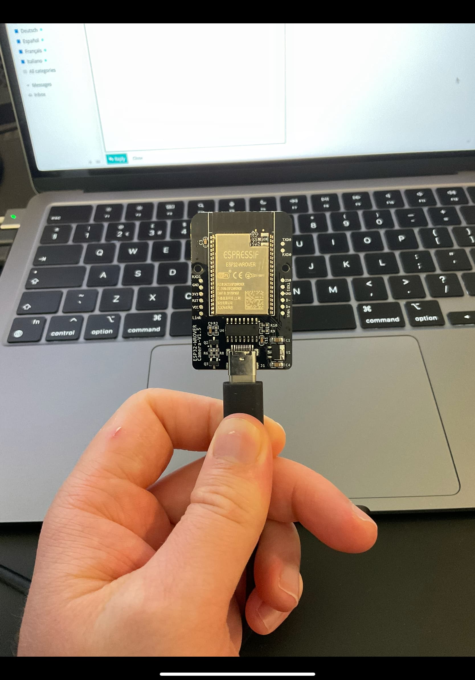
Sorry I should have been more specific, I was referring to the ESP32 Wrover board. When plugged in directly, the LEDs are not on, nor does the WiFi network appear on my computer. It only appears to be working when it is plugged into the IO extension board. Here are images of it:
Further evidence is that the pins are labeled "RX" and "TX" on the PCB silkscreen. A USB socket doesn't have RX and TX pins so it would not make any sense for someone to label the pins this way. It would make perfect sense to do so if the connector was instead used for a serial interface between the UNO R3 derivative board and the ESP32 microcontroller on the camera module (and using USB for this interface would not make any sense at all).
It looks like you just jammed a USB cable into a connector that happened to have dimensions that are somewhat similar to USB. That will never work! This explains why the upload was failing.
You might have bent some of the contacts in the connector when you did that. You should carefully remove the USB cable from the connector and then do a close visual examination of the contacts in the housing. If they appear bent, try to carefully correct their alignment. Otherwise you might severely damage them when you insert the real plug into the connector.
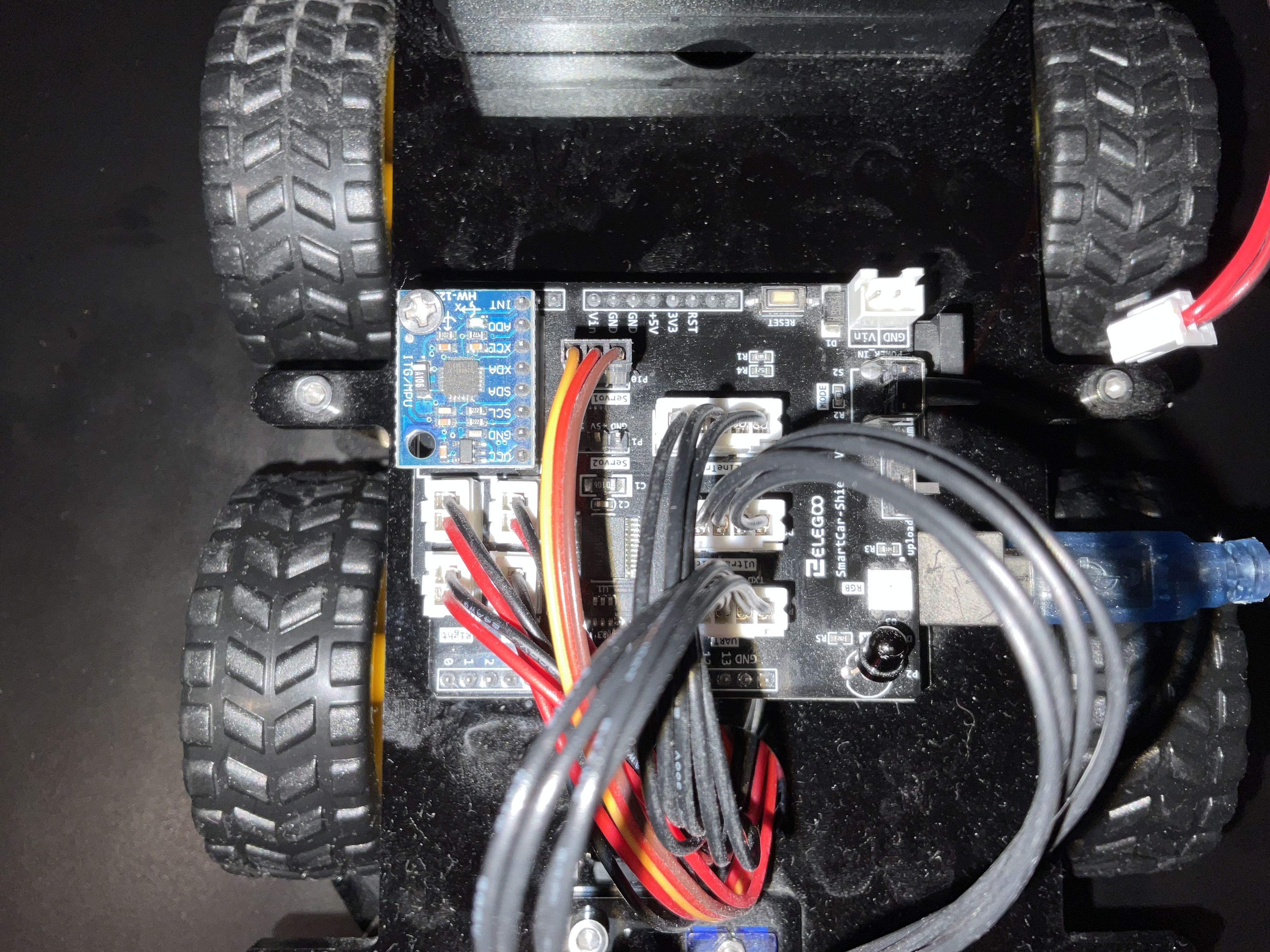
Sorry I took the picture with the board the wrong way around! Dont worry, I didn't jam the USB into the socket! The USB connector is on the back of the board. I was just trying to show how the board only appears to be on when plugged into the IO extension board. I've retaken the pictures.
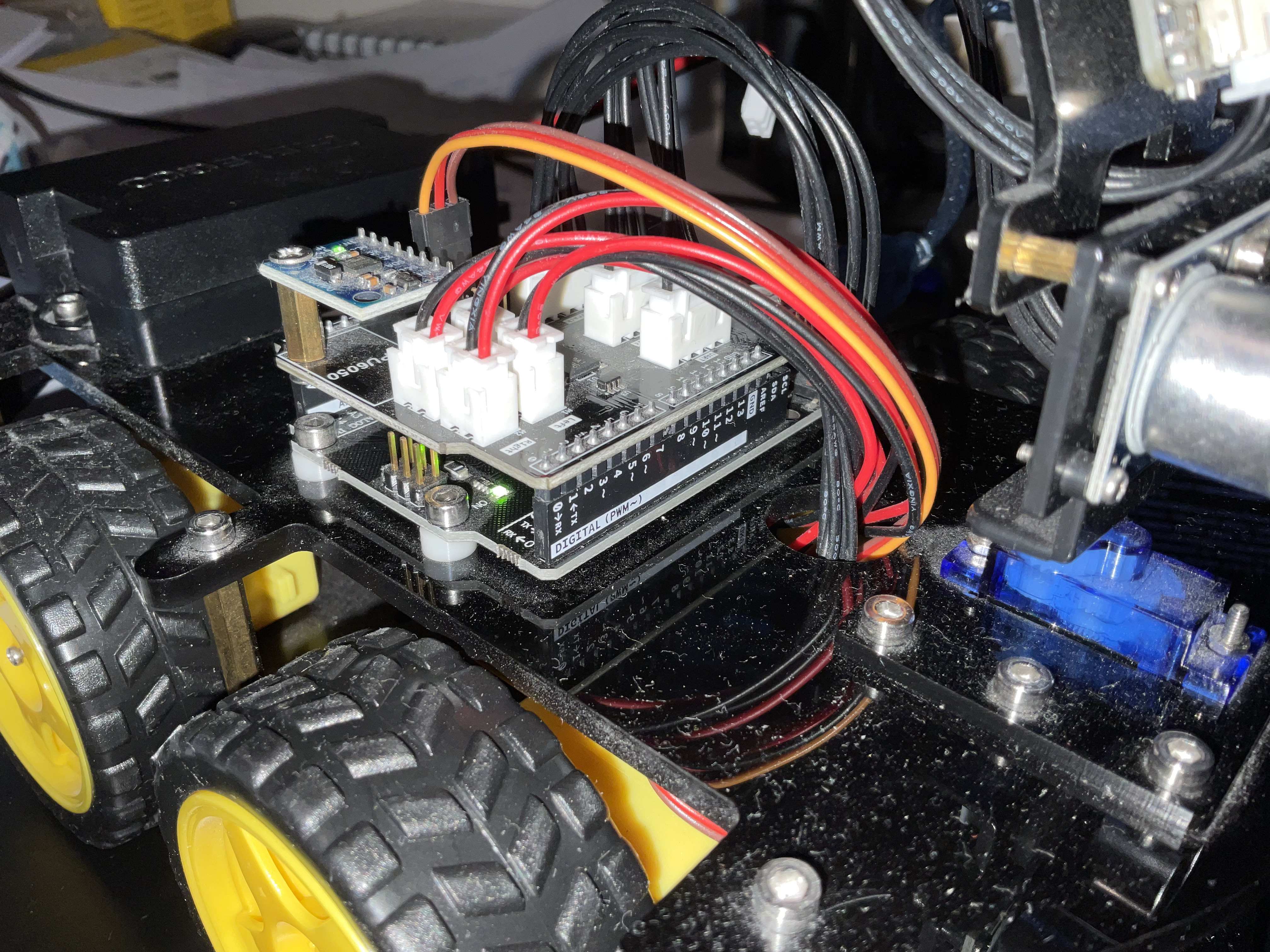
Here is the board appearing to be on when plugged into the IO extension board:
It is cool that they put a USB interface on the camera module! My assumption was that the board only had a serial interface, as is the case with the standard "ESP32-CAM" boards (which are typically used with a separate "motherboard" that provides the USB interface). They went the extra mile to spend more on extra components that were not absolutely necessary in order to make it easy for the user to update or modify the firmware on the camera module's ESP32.
It is not clear what the LEDs on the camera module are intended to indicate as the labels on the silkscreen don't provide any useful information (the "D1" and "D2" labels are just the component identifiers from the module's schematic). There is a small possibility that these LEDs are not power indicators, but rather indicators for the RX and TX activity. In that case, it could be expected that they wouldn't light up when only the USB cable is connected, even though the board is powered.
So if you want to continue to try to troubleshoot this, I can make another suggestion:
Please try this troubleshooting procedure and then report your results in a reply on this forum thread:
This procedure is not intended to solve the problem. The purpose is to gather more information.
Unplug the USB cable of your Arduino board from your computer if it is currently connected.
Click the Apple logo on the left side of the menu bar at the top of the screen ("Apple menu").
Select "System Settings..." from the menu.
A "System Settings" window will open. Click "General" in the menu on the left side of the window. ⓘ You may need to scroll the menu down to see "General".
Click "About" on the panel at the right side of the "System Settings" window.
The "About" panel will open. Click the "System Report..." button at the bottom of the panel.
The "System Information" window will now open. Select Hardware > USB from the tree on the left side of the window.
Take note of the contents of the "USB Device Tree" panel of the "System Information" window.
Connect the Arduino board to your computer with a USB cable.
Select File > Refresh Information from the menu bar.
Do you see any new device appear in the "USB Device Tree" panel of the "System Information" window after doing the last step?