I tried out a couple of tools yesterday, including MacSpice. I downloaded iCircuit from the App store and I am somewhat underwhelmed by it. Don't get me wrong, it has a nice GUI, a number of elements that can be added easily (everything from simple circuit components up to ADCs) but there are several improvement opportunities. For example, only one scope window can be opened. OK if the signal amplitude is similar, not so great if you're trying to monitor two very different signals at the same time (i.e. current on one probe vs. volts on another). Worse, the current version on my CPU will allow me to save designs but not to re-open them later. Kinda defeats the purpose of the save function, no?
Anyhow, I thought I'd include another screenshot. This one includes the transformer though I have to admit that I did not include the internal resistances of the transformer because they were not listed by the manufacturer on the datasheet. So the current flowing through the primary is somewhat fantastical. That aside, I thought it was very interesting that there was only a very small marginal difference between using a 10uF coupling cap vs. using a 100uF coupling cap in terms of transferred signal. The DC was still kept out - note the 100VDC offset I put into the power supply. I also got similar results when I omitted the transformer and used a AC signal source directly on the resistors that would have been attached to the secondary side of the transformer.
A 10uF capacitor is a lot cheaper and smaller than a 100uF capacitor but I worry that this sort of analysis may be oversimplifying what is really going on. The 100MOhm resistor all the way to the right is to represent the ADC, which is where I am getting this 'scope' image from. The input has a max amplitude of 177VACrms with a 100VDC offset, which transfers nicely. The secondary shows a 20Vpp with a 4VDC positive offset. Seems to make sense given the inputs. I have placed a 150V MOV ahead of the transformer on my PCB. So I'd like to think that the circuit wouldn't ever come close to a continuous 170+VACrms input.
Do you think I should stick to the 100uF ceramic capacitor or breadboard the circuit above on a existing Mini that has already lost one ADC channel due to earlier mishaps with voltage dividers?
Constantin:
Do you think I should stick to the 100uF ceramic capacitor or breadboard the circuit above on a existing Mini that has already lost one ADC channel due to earlier mishaps with voltage dividers?
Although reducing the 100uF capacitor to 10uF only reduces the voltage slightly, it causes extra phase shift. If you are trying to measure power by monitoring voltage and current, then you need to take account of the phase between the voltage and current. So you need to minimise the phase shift in the voltage you are sampling. A lower value capacitor will cause more phase shift. I would increased the values of all the resistors by a factor of 10 or 20, to reduce the effect of the capacitor on the phase shift, and also to reduce the current through the protection diodes when transients occur on the input. The 22 ohm resistor does nothing useful and might as well be removed. You could also remove the lower resistor (currently 1K) in the voltage divider if you increase value of the upper one (currently 2K2) by 50%.
The voltage at the Arduino input pin will still go negative at startup with that design, until the capacitor has charged sufficiently. This is not a problem if you are limiting the input current to a sufficiently low value.
There will also be a small phase shift due to the magnetising current of the transformer and the resistance of its primary.
It's the weirdest thing, my iPhone is showing me a longer reply from you earlier, but the web site does not. Anyhow, you brought up some very good points about startup conditions and whether the BAV99's can actually do anything to protect the Atmega input pins.
One solution I thought of (but cannot implement yet thanks to the iCircuit program being on strike again) is using a small triac or SSR in series with the coupling capacitor separating the transformer output from the Arduino. Tie the gate to the 2.5VDC power supply via a 10k and the thing should only conduct whenever there is AREF power. Alternatively (and perhaps smarter) tie the gate to a digital pin so that the analog input into the atmega can be interrupted at will - i.e. detect a high voltage condition and turn the thing off... The question is whether a triac or SSR would have an impact on the signal.
I tried out the circuit with components that have a 10x higher resistance and naturally that works also. Based on the new reply from you (that popped up while I was writing this) I will retain the 100uF capacitor.
Interestingly, iCircuit reports a signal across a NO standard relay being possible even if the coil is not energized. Makes me reconsider some of the other outputs as well! Perhaps time to return the product in favor of the other circuit analysis tool on offer in the App store.
Constantin:
It's the weirdest thing, my iPhone is showing me a longer reply from you earlier, but the web site does not.
That's because I edited my reply just after posting it, because I misinterpreted what your simulation was showing - sorry!
Constantin:
Anyhow, you brought up some very good points about startup conditions and whether the BAV99's can actually do anything to protect the Atmega input pins.
BAV99's will take some of the current away from the Arduino protection diodes, but what proportion they take is not very predictable. Shottky diodes would be better. OTOH if you use a high enough source resistance, the current will be limited to a safe value for the internal protection diodes anyway.
Constantin:
One solution I thought of (but cannot implement yet thanks to the iCircuit program being on strike again) is using a small triac or SSR in series with the coupling capacitor separating the transformer output from the Arduino. Tie the gate to the 2.5VDC power supply via a 10k and the thing should only conduct whenever there is AREF power. Alternatively (and perhaps smarter) tie the gate to a digital pin so that the analog input into the atmega can be interrupted at will - i.e. detect a high voltage condition and turn the thing off... The question is whether a triac or SSR would have an impact on the signal.
Yes, it would have a big input on such a low voltage signal. Better to design the circuit so that negative inputs during startup will not damage it or cause it to malfunction. It needs to handle negative input anyway because of transients on the mains supply.
Constantin:
I tried out the circuit with components that have a 10x higher resistance and naturally that works also. Based on the new reply from you (that popped up while I was writing this) I will retain the 100uF capacitor.
If you use two 22K resistors to generate the 1.25v bias, then you should find that connecting the transformer through a capacitor and a 68K resistor (omitting the lower resistor in your potential divider) will give you the required signal level. The capacitor then only needs to be large enough to have an impedance that is much smaller than 79K at 60Hz. A 10uF capacitor will then be high enough to give you negligable phase shift.
BTW to reduce the affect of transients, I suggest you do one or both of the following:
Instead of a single 68K resistor, use two 33K resistors, one in series with each end of the secondary. This will reduce the current induced on the ground line when a transiant is capacitively coupled between primary and secondary.
Ground the core of the transformer directly to the power supply ground.
I decided to try out a couple of configurations based on your suggestions that I hope I interpreted correctly.
I have enclosed two screenshots that I hope are interesting / useful... It occurred to me that the protection diodes would have a hard time protecting as long as their forward voltage potential wasn't adjusted. So, I created yet another voltage divider that may be just gilding the lily for all I know. I am assuming Schottky's here, 0.222Vdrop at 1A. iCircuit is extremely limited re: inputs in the interest of simplicity. I hope that it accounts for the different forward voltage drops in diodes as a function of current but I'm not super confident it does!
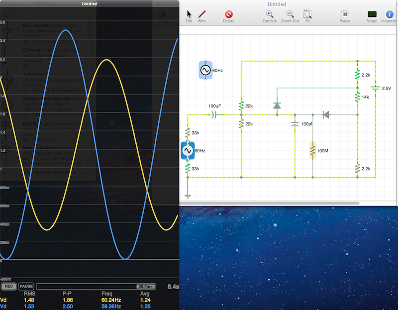
The first screenshot shows conditions under nominal 115VACrms conditions. I.e. the secondary voltage amplitude of the transformer is 6.5V (4.6VACrms*1.41), offset for fun by 2VDC. The yellow line on the 'scope' shows the voltage drop across the 1M resistor that stands in for the ADC while the blue line is a idealized VAC supply with an amplitude of 1.25 and a DC offset of 1.25V.
At 115VACrms the inputs into the ADC look pretty good. The curves are nicely formed, I see no distortion. Now, lets try a 230VACrms input. Note how the diodes are getting a workout and how the tips of the ADC violtage curves are getting compressed. There are no excursions above 2.5VDC or below 0VDC (so the ADC is safe). Then there is 150V MOV... Not sure if it's strong enough to blow a 1A slow-blow fuse before it goes boom, however.
That aside, the above looks promising. But I don't trust this program enough to accept the above as gospel. Any SPICE programs out there with a good GUI as long as it's either Mac or Windows? I'd like to think that WinSPICE would allow you to adjust component behavior with a bit more granularity.
Using protection diodes as shown here takes some fairly careful calibration. I looked up some schottkys that had a similar form factor as the BAV99 (SOT-23) Their 1A voltage drop is about 0.45V @ 25*C but forward voltage is a function of current and temperature, as their datasheet shows on page 2.
I re-ran the circuit analysis tool and I wonder if those here who have way more experience than me can weigh in... Attached below is a 'scope' output and the circuit, which I am overdriving 100%, i.e. 230VACrms input on the primary side resulting in a 13VACpp signal on the secondary side. The green and blue 'scope' lines are for the protection diode, the red line shows the ADC voltage.
Extrapolating the chart in the datasheet that Diodes Inc published, I would expect about a 0.1V voltage drop at 0.1mA. The 'scope' appears to confirm this, as the peak forward current is around 120uA, while the 'shaven' portion of the voltage is about 0.15V, which looks consistent. However, if I disable the diodes by increasing their forward voltage to 1000V, the Vpp across the ADC is 4.77V. That suggests to me that each diode is actually shaving off more than a volt. So isn't this inconsistent? At a forward voltage of 1V, the SOT23 should be blowing up (i.e. 4+Amps). Granted, this is not a steady-state condition but still...
I have yet to build a linear opto-isolation circuit. For me, they've always been either the on or the off type, usually with an AC input stage to make them universally applicable. I always thought that linear opto-isolation circuits require a lot more components to keep things linear... so that circuit of yours certainly looks interesting... I have no ability to model optos right now as neither circuit modeling package I have here can handle them outright... some vendors of linear optos like AVAGO go as far as including a SPICE model in their documentation.
As for Eagle, I chose that package since it's the most intuitive one I could find that ran on Windows as well as Mac computers. The large parts libraries available on the 'net are nice too, though all vendors could do a better job of documenting their wares. I frequently find myself coming up with parts libraries for my projects because the chips are not defined elsewhere. My biggest gripe with Eagle isn't though with the clunky UI or the somewhat arbitrary process flows (to define a new part, for example). It's the auto-router, which I find pretty useless.
However, thanks to the free-routing project, I have access to an amazing auto-router that is great for initial layout optimization, even if I later lay out a board on my own. I wish Cadsoft could buy a license from those researchers, as that autorouter makes the one in Eagle look pathetic, even if there are some quirks that have yet to be worked out (i.e. orphaned polygons, etc.).
Post-script: I hope to assemble the last revision of this circuit this weekend and compare its output / performance vs. that of a circuit with a differential input and a dedicated external 12-bit ADC.
Also, with the help of my console logs Frank Krueger has identified and eliminated the issues associated with loading and saving iCircuit files properly on the Mac. It now functions as expected. I highly recommend this program to anyone who would like to simulate complex or dynamic inputs into systems. While one doesn't get the satisfaction of smoking yet another ADC, it's a lot easier (and cheaper!) to troubleshoot a simulation up front than to dispair over a non-functioning system later on.
Interestingly, the output of the transformer is actually higher than expected. Instead of a no-load voltage of around 4.8V, it's actually features 6VACrms output with a 120VACrms input. So I adjusted some of the resistor values accordingly. Additionally, the circuit was redesigned for operation with up to 230Vrms plus a 25% safety margin, above which the protection diode kicks in.
The maximum design voltage into the ADC will range from 0-285VACrms on the input side of the transformer and 0.5-4.5V for the ADC input. In the process, I am essentially leaving 1V of measurable voltage range on the table but given that I've adopted a ADC122S625 12-bit external ADC, the extra bits still allow me to resolve to about <0.2V and <0.02A absolute, i.e. plenty close for Watt measurements (<0.01W).
I also changed around the protection circuit to feature a 5.1V zener diode. Using various circuit simulators, I adjusted the voltage divider and biasing resistors on the low-voltage side of the coupling-capacitor. Note how they are not the same value, but they do provide a 2.5V-centered signal. The odd resistor values are governed by what is available in a 0805 package.
CHA- and CHB- are the other end of the two differential inputs. Given the confusing language in the datasheet on what allowable voltage ranges can be used for differential operation, I elected not to use differential inputs for the voltage signal (the current signal is unipolar by design). The Vref voltage governs the allowable range above and below the common mode voltage, which is input on the CHA- and CHB- channels, respectively. Since I found the signal on the S22P to be very reliably centered at 2.5V, I elected to use the 2.5V signal from a small local regulated power supply to also supply the CHA- pin.
However, since CHB+ inputs are dependent on the local 5V power supply (which may fluctuate, depending on what is powering the Arduino) I chose to power CHB- with a voltage divider that is dependent on the 5V rail. The 0.1uF capacitor keeps the supply stable and the noise out...
And now for another attempt, this time using the differential inputs as intended. I cribbed figure 7, i.e. section 3.6 from this discussion in this nifty TI publication regarding the use of buffers and ADCs. However, I omitted the buffer, perhaps in the mistaken belief that I would not need it for something as 'slow' as a 60Hz AC mains signal (made safe via a transformer).
This is the circuit, introducing a 2.5VDC bias based on a 4.096VDC series reference into the AC signal. Does this look OK? The simulator says "go" but I wonder if I have considered everything.
For example, should my 120 to 6VAC transformer have a ground associated with the center of the secondary winding? It currently does not, i.e. it 'floats' and yet this DAQ is powered by a switch-mode power supply. Other transformer designs feature split secondaries presumably for this purpose. Since the ADC is not powered by a battery system, I presume I should have a center tap on the transformer?
Also, how best to model the impedance / capacitance of the ADC? As you may recall, I am using the ADC122S625 which has no listed impedance but whose datasheet suggests a 20pF input capacitance during tracking. Is 100k a good start regarding the input impedance of the ADC?
And if my query re: the transformer was clear as mud, here is a updated picture / circuit diagram. As to the why, see p. 17 in this Analog Spec Sheet for the AD8222.
The output voltages have changed somewhat from the transformer (only available in a 2x12VAC output version vs. the 6VAC in the previous design) hence the slightly different drop resistors. Interestingly enough 2x12VAC @ 230VAC input = 67Vpp at no load (= 2x 19.1VAC) on the output pins of that transformer once you add a 25% overage allowance. Yikes!