I have a sensor that runs on 12VDC.
When I connect my voltmeter up to it I connect the voltmeter ground and the sensors 12v ground together and voltmeter red cable to the Signal wire of the sensor.
This works.
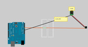
When I connect my arduino from Analog 0 to Signal on the sensor and +and- on the sensor to a 12v wallwart the arduino bounces all over the place. I assume I need the grounds to be common to the signal can complete the loop?
So since the walwart is 12V can I do that or will it torch the arduino?
Yes, you need the grounds connected together. The signal coming from the sensor is only 0V-5V so it's OK that the wall-wart is 12V. You can always add a 1k (or so) series resistor (sensor-->1k resistor-->analog 0) for extra safety.
--
The Gadget Shield: accelerometer, RGB LED, IR transmit/receive, speaker, microphone, light sensor, potentiometer, pushbuttons
still getting a nasty bounce. Maybe Ill try the resistor to to smooth it.
Also going to add the voltmeter back inline (in series) to see if the output from the sensor is jumping. (i dont think so)
yep had a brain freeze and had to figure out inline again... Now to dig out a resistor. i should really use that 100 drawer case and separate these things.
and note the value for your two known values (these have to be integers, but if they are 0.05 you just use 500 then you know that you divide the reported integer value by 10000 to get the float value).
Say the Arduino say 315 and 873 for the saline values 0.05 and 1.2 (I have no idea if these values are reasonable - I'm just making some up)
Then write the real program where the output is
Code:
Yea I want to Serial.println( analogRead(0) ) ; (ValueA) At a known salinity of 1000uS and then Serial.println( analogRead(0) ) ; (ValueB) At another known salinity of 2000uS.
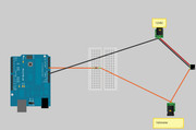
No no no. Your voltmeter is connected very very very wrong.
Do you know the difference between Current and Voltage?
And your circuit is complete BS.
Try to:
-use angled wires in your drawing don't make them cross eachother
-add "+", "GND" and "SIG" signs so we know what is what
-add voltages, 3.3V, 5V, 12V
-not to use terms that you don't understand
And finally, what is that sensor? Type, manufacturer, link to datasheet
Now, what is wrong with the placement of the meter? You really need to assimilate with the basics of the electronics.
when running at 5 second intervals. lowering and raising the interval of delay doesnt change it.
The sensor doesnt have a datasheet. It was custom made for me by somebody. They took one of their current sort of home brew designs and converted it to a 0-5VDC signal. Not a lot of testing was done on it and the guy doesnt have an arduino. he was just using a voltmeter. Using a voltmeter it works.
For example:
I get a reading of 1.890VDC.
My linear slop has a formula of (.2054 +y) / .0008 = x
so X=2619.25
X=Total Disolved Solids in a liquid in microsiemens
My Hanna TDS meter reads 2550uS
Thats a difference of 69.25uS or 34.625 Parts Per Million. Pretty darn close!!
Definitely in the "good enough for government work" range. When accounting for the accuracy/resolution of both the Hanna meter and the custom meter and temperature compensation in both.
So sorry to be long winded, I always hope these posts help somebody else as I get most of my knowledge from reading somebody elses posts.
I put in a 1k resistor between sensor signal and arduino. Voltage dropped just a little and is stable on the voltmeter but arduino is still giving erradic results.
I decided to try a different input as well. A5. same thing.
Im going to get out my Uno and try it. Maybe I dropped this Duemolove a few to many times.
A resistor does not "smooth" a fluctating voltage. A resistor-Capacitor circuit will do so.
IF (I am making assumptions here) the voltage meter is showing a steady voltage, and the Arduino is showing erratic values I can think of two possible causes: You ar not using the right pins (and the program is reporting an opencircuit/nonsense value) or your physical construction of the circuit is not solid enough, there is a loose connection.
We might get this kind of problem if the sensor is not outputting a single steady voltage level, but some pulsetrain or there is some other "noise" on the line. The voltage meter takes long samples, ie. it sort of shows an average voltage level. The Arduino ADC is a lot faster and might truly sample the voltage. Only way to know is to use an oscilloscope. (Or use an RC circuit...but then we move into a whole new set of problems)
Could you get your friend to write a little/short description of how/what his sensor is doing, which you then include here?
(NB: Have you tried the Scandianvian Forum where you can write in Finnish?)