AD590 Temperature Sensor Reading

I hope you're doing well. I'm currently working on a project involving the AD590 temperature sensor for data logging temperatures over multiple days. My primary goal is to calculate the standard deviation of the recorded data, so absolute values are of lesser importance to me at this stage.

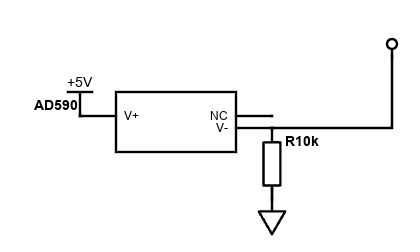
Below is the schematic I'm currently using:

Scheme-it-export-New-Project-2024-06-07-16-38

However, I've encountered a significant issue where the values seem to fluctuate quite a bit. Here are some examples of the readings I've obtained:

.722 V, 272.24 K, -0.91 °C, 30.36 °F
2.722 V, 272.24 K, -0.91 °C, 30.36 °F
2.727 V, 272.73 K, -0.42 °C, 31.24 °F
2.722 V, 272.24 K, -0.91 °C, 30.36 °F
2.727 V, 272.73 K, -0.42 °C, 31.24 °F
2.610 V, 261.00 K, -12.15 °C, 10.12 °F
2.727 V, 272.73 K, -0.42 °C, 31.24 °F
2.722 V, 272.24 K, -0.91 °C, 30.36 °F
2.717 V, 271.75 K, -1.40 °C, 29.48 °F
2.722 V, 272.24 K, -0.91 °C, 30.36 °F
2.630 V, 262.95 K, -10.20 °C, 13.64 °F
2.439 V, 243.89 K, -29.26 °C, -20.67 °F
2.175 V, 217.50 K, -55.65 °C, -68.17 °F
2.146 V, 214.57 K, -58.58 °C, -73.45 °F
2.092 V, 209.19 K, -63.96 °C, -83.13 °F
2.160 V, 216.03 K, -57.12 °C, -70.81 °F
2.713 V, 271.26 K, -1.89 °C, 28.60 °F
2.493 V, 249.27 K, -23.88 °C, -10.99 °F
2.190 V, 218.96 K, -54.19 °C, -65.54 °F
2.732 V, 273.22 K, 0.07 °C, 32.12 °F
2.498 V, 249.76 K, -23.39 °C, -10.11 °F
2.722 V, 272.24 K, -0.91 °C, 30.36 °F
2.717 V, 271.75 K, -1.40 °C, 29.48 °F
2.727 V, 272.73 K, -0.42 °C, 31.24 °F
2.722 V, 272.24 K, -0.91 °C, 30.36 °F
2.732 V, 273.22 K, 0.07 °C, 32.12 °F
2.688 V, 268.82 K, -4.33 °C, 24.20 °F
2.727 V, 272.73 K, -0.42 °C, 31.24 °F
2.722 V, 272.24 K, -0.91 °C, 30.36 °F
2.717 V, 271.75 K, -1.40 °C, 29.48 °F
2.732 V, 273.22 K, 0.07 °C, 32.12 °F
2.727 V, 272.73 K, -0.42 °C, 31.24 °F
2.722 V, 272.24 K, -0.91 °C, 30.36 °F
2.727 V, 272.73 K, -0.42 °C, 31.24 °F
2.722 V, 272.24 K, -0.91 °C, 30.36 °F
2.727 V, 272.73 K, -0.42 °C, 31.24 °F

Despite using a stable power source (an expensive 5V laser power supply) to mitigate noise, the problem persists. Additionally, the resolution of the readings is insufficient for my needs, which is why I've ordered a 24-bit ADC.

Could anyone shed some light on what might be causing this issue or offer suggestions on how to rectify it? Any insights or guidance would be immensely appreciated. Thank you!

Code?

Do you have to use that sensor ?

It is ±0.5°C accurate. That is nothing special.
Which Arduino board do you use ?

The sensor outputs a certain current for a certain temperature.
The 5V powering the sensor should have no influence.
The Arduino should have its analog reference set to a (internal) reference voltage, because the voltage over the resistor has to be read.

Do you have a multimeter ? To measure the voltage over the resistor.
If you use a breadboard, then it can have bad contacts. Jumper wires can be broken.

Connection diagram?

No code, so let's go with the hundred guesses.
No averaging, averaging faulty, poor pin management, sloppy power connections, other code interference, unreasonable expectations, poor data type choices.... and any number of other possibilities.

Yes I would prefer to use this sensor. I have about 20 of them laying around and would like to use them haha. The accuracy isnt a big deal, but the precision/repeatability is whats most important to me.

I use the arduino uno R3.

Yes I have a multimeter. The voltage over the resistor is the same as what's showing in the arduino logs (minus 20 or so mV). The current is also showing as being 288uA which is right based on the room temperature im at.

I was using a breadboard, I will swap off of it. I plan on making a few PCBs with this sensor in the future.

Thank you for your advice.

Turns out I got rid of a lot of noise by powering it with the 5V Barrel jack and my bench top power supply.

Unfortunately my PC shut down (I was adjusting some cables) and I lost the code... I had not saved it yet... lol.

I will try and write some new code within the next few days and get back to you.

I ended up writing something new. Slightly better but I have no way to test it as I'm not near my arduino until Tuesday when I return home.

// Constants
const int sensorPin = A0;  // Analog input pin 
const float resistorValue = 10000.0;  // Resistor Value
const float voltageReference = 5.0;  // Reference voltage
const int numReadings = 10;  // Number of readings

// Variables
int readings[numReadings];  // Array to store readings
int readIndex = 0;  // Index of current reading
float total = 0;  // Total of readings
float average = 0;  // Average of readings

void setup() {
  Serial.begin(9600);
  
  // Initialize all the readings to 0
  for (int i = 0; i < numReadings; i++) {
    readings[i] = 0;
  }
}

void loop() {
  // Subtract last reading
  total = total - readings[readIndex];
  
  // Read input on analog pin 0
  readings[readIndex] = analogRead(sensorPin);
  
  // Add reading to total
  total = total + readings[readIndex];
  
  // Advance to next position in array 
  readIndex = readIndex + 1;
  
  // If at end, wrap around to beginning
  if (readIndex >= numReadings) {
    readIndex = 0;
  }
  
  // Calculate average
  average = total / numReadings;
  
  // Convert average to voltage
  float voltage = average * (voltageReference / 1023.0);
  
  // Calculate current through the resistor
  float current = voltage / resistorValue;  // I = V / R
  
  // Calculate temperature in Kelvin
  float temperatureKelvin = current * 1e6;  // Convert from A to uA
  
  // Convert Kelvin to Celsius
  float temperatureCelsius = temperatureKelvin - 273.15;
  
  // Print out the temperature
  Serial.print("Temperature: ");
  Serial.print(temperatureCelsius);
  Serial.println(" °C");
  
  // Wait for a second before next reading
  delay(250);
}

Sorry to hear that. Let us know precisely how the new code performs, and remember to post a new version if you make changes.

The barrel jack requires a minimum of 7 volts to supply the onboard voltage regulator. If you have a good 5 v supply you can connect it to the 5 volt pin on th Uno.

For the best stability use either an external voltage reference or the reference internal to the microcontroller (I forget what voltage it is). The default reference is the 5 volt supply which can be very noisy.

Your resistor should have a very low temperature drift too.

I see. Thank you for that information. I only supplied 5 volts to the DC barrel jack so I am unsure as to how that worked. I can just supply 7V next time.

Would that make a difference from supplying 5V to the 5V pin on the uno?

I think i'm going to supply 7V to the barrel jack with my power supply, and then I will use the less noisy 1.1V internal reference with a 24 bit ADC and a 2.3k resistor. This should give me much higher resolution and stability?

EDIT: I actually think i should use the reference voltage from my ADC

Absolute (accurate) supply voltage is not important with this sensor, because it's basically a current source. Just power it from Arduino's 5volt supply, with Aref set to 1.1volt.
1.1volt Aref, a ~3k resistor, and a 5volt supply also ensures a minimum sensor headroom of 4volt, which your original diagram (5volt/10k) does not.

There is a voltage difference of 3mV per degree C with a 3k sense resistor, which gives you about three A/D values per degree C with 1.1volt Aref. Not enough for one decimal place...
An ADS1115 (15-bit) would be a better companion for this sensor. I don't think you can do much better. The weak point of a 24-bit A/D could be a stable reference voltage.
Leo..

1 Like

This topic was automatically closed 180 days after the last reply. New replies are no longer allowed.