Trying to implement a DAC
A few tutorials on ways to do it below that I am following:
How to use MCP4725 12-Bit DAC Module with Arduino
Downloads | MCP4725 12-Bit DAC Tutorial | Adafruit Learning System
The first tutorial uses and UNO in this configuration
In this configurtion SCL/SDA come from A4/A5

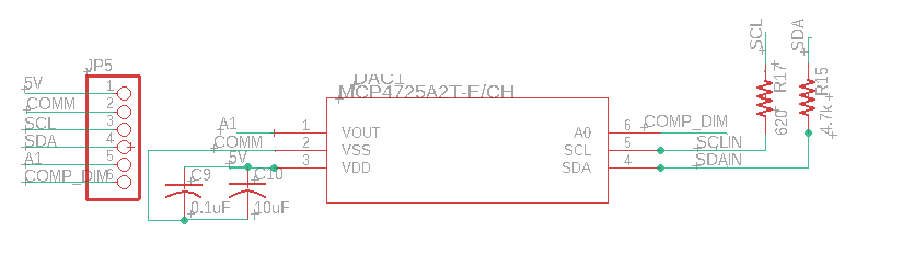
It appears the pinout I made in the schematic is different
This matches the device we are using
It is an UNO

The UNL we are using is made by this company
Ruggeduino-ET "Extended Temperature" -40C - 85C — Rugged CircuitsRugged Arduino
I have tried to run the demo code but nothing is connecting / working
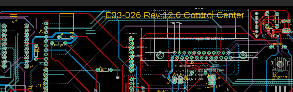
For reference this is the schematic

some code
 /*

 */
 #include <Wire.h>
#include <Adafruit_MCP4725.h>
Adafruit_MCP4725 dac;

#define digitalPin2 2   // Port 2 for reading the door interlock state
#define digitalPin4 4   // Port 2 for turning on the cabinet LEDs
#define digitalPin6 6   // Port 6 for Power LED on light field alignment
#define digitalPin8 8  // Port 8 for slecting dimming method
#define digitalPin10 10   // Port 10 for Green LED on filter
#define digitalPin12 12   // Port 12 for Green LED on filter
#define digitalPin13 13   //  Port 13 for reading the push button on the light field module
#define DAC_RESOLUTION    (9)   // Set this value to 9, 8, 7, 6 or 5 to adjust the resolution
 #define potentiometerPin A1


int x =0;
int interlockstate=0;
int pushbuttonlightfield=0;
int analogPin = A5;
int Thumb_Dimmer_Pin = A1;
int Thermo_Pin = A2;
float rawvalue=0;
float rawvalue2=0;
float rawvalue3=0;
float voltagevalue=0;
float Thumbvoltagevalue=0;
float Thermovoltagevalue=0;
//ISR//float value = 100;   //3035;


void setup()
{

  Serial.begin(9600); //begin serial data
   pinMode(digitalPin2, INPUT); // Port 2 for reading the interlock state
   pinMode(digitalPin4, OUTPUT); // Port 4 for Cabinet LEDs
   pinMode(digitalPin6, OUTPUT); // Port 6 for Power LED on light field alignment is an output
   pinMode(digitalPin8, OUTPUT); // Port 8 for Dimming method select is an output
   pinMode(digitalPin10, OUTPUT); // Port 10 for Green LED on filter is an output
   pinMode(digitalPin12, OUTPUT); // Port 12 for Yellow LED on filter is an output
   pinMode(digitalPin13, INPUT); // Port 13 for reading the push button on the light field module
   //pin 13 is not on an interrrupt for state change so might need to change the switch
}


void loop()
{

      delay (500);    //rev 3, delay to slow system down

      //Read this to see if the push button to turn on the LED is pushed or not
       pushbuttonlightfield =  digitalRead(digitalPin13);
     //     Serial.print("Push button state (0 is not pushed): ");
    //      Serial.println(pushbuttonlightfield);

  //check if serial communication is avaiable
    //then issue responce if command recognized
    //using println rather than print so there is new line feed issued
    //took this part from Filter recogition code
  if (Serial.available() > 0) {
      String rx_byte = Serial.readStringUntil('\n');
        rx_byte.trim();

        if (rx_byte == "CMD1") {
            digitalWrite(digitalPin12, LOW); // turn off  Yellow LED in filter module
            Serial.println("SUC1");      //CMD1 responce
        }
        if (rx_byte == "CMD2") {
            digitalWrite(digitalPin12, HIGH); // turn on Yellow LED on filter module
          Serial.println("SUC2");      //CMD2 responce
        }
        if (rx_byte == "CMD3") {
          digitalWrite(digitalPin10, LOW); // turn on Green LED on filter module
          Serial.println("SUC3");      //CMD2 responce
        }
        if (rx_byte == "CMD4") {
          digitalWrite(digitalPin10, HIGH); // turn on Green LED on filter module
          Serial.println("SUC4");      //CMD2 responce
        }
       if (rx_byte == "CMD5") {
          digitalWrite(digitalPin8, LOW); // Set Dimming method to Analog
          Serial.println("SUC5");      //CMD2 responce
        }
       if (rx_byte == "CMD6") {
          digitalWrite(digitalPin8, HIGH); // Set Dimming method to Digital
          Serial.println("SUC6");      //CMD2 responce
        }
       if (rx_byte == "CMD7") {
          digitalWrite(digitalPin6, HIGH); // turn on Power LED on light field alignment module
          Serial.println("SUC7");      //CMD2 responce
        }
       if (rx_byte == "CMD8") {
          digitalWrite(digitalPin6, LOW); // turn off Power LED on light field alignment module
          Serial.println("SUC8");      //CMD2 responce
        }
     if (rx_byte == "CMD9") {
          interlockstate  =   digitalRead(digitalPin2);  // 0 door open, 1 door closed
          Serial.println(interlockstate);  //(0 is door open)
        }
      if (rx_byte == "CMD10") {
        rawvalue = analogRead(analogPin); // voltage Primary Trimpot:
        voltagevalue = rawvalue*(5.00)/1023.00;
         Serial.println(voltagevalue, 3); // Print voltage with 3 decimal places
        }
        if (rx_byte == "CMD11") {
           rawvalue3 = analogRead(Thermo_Pin); // Read the analog input from thermocouple
           Thermovoltagevalue= rawvalue3*(5.00)/1023.00;
         Serial.println(Thermovoltagevalue, 3); // Print voltage with 3 decimal places
        }
       if (rx_byte == "CMD12") {
         rawvalue2 = analogRead(Thumb_Dimmer_Pin); // Read the analog input from thumb wheel
        Thumbvoltagevalue = rawvalue2*(5.00)/1023.00;
         Serial.println(Thumbvoltagevalue, 3); // Print voltage with 3 decimal places
        }
       if (rx_byte == "CMD13") {
          digitalWrite(digitalPin4, HIGH); // turn off Power LED on light field alignment module
          Serial.println("SUC13");      //CMD2 responce
        }

       if (rx_byte == "CMD14") {
          digitalWrite(digitalPin4, LOW); // turn on Power LED on light field alignment module
          Serial.println("SUC14");      //CMD2 responce
        }
       if (rx_byte == "CMD15") {

           //      https://how2electronics.com/how-to-use-mcp4725-12-bit-dac-module-with-arduino/
           //    https://learn.adafruit.com/mcp4725-12-bit-dac-tutorial/download
          // make sure to install Installed Adafruit MCP4725@2.0 before compiling

          dac.setVoltage((1 * 4095) / 5, false);    //Set voltage to 1V
          delay(2000);
          dac.setVoltage((2 * 4095) / 5, false);    //Set voltage to 2V
          delay(2000);
          dac.setVoltage((3 * 4095) / 5, false);    //Set voltage to 3V
          delay(2000);
          dac.setVoltage((4 * 4095) / 5, false);    //Set voltage to 4V
          delay(2000);
          dac.setVoltage(4095, false);              //Set voltage to 5V or (Vcc)
          delay(2000);
        }


  }

}
Any thoughts on how to fix this?


