Hi guys,
I’m working on building a lightning trigger that triggers a camera whenever a light sensor sees a lightning strike. I found some code online that unfortunately is written in Assembler but I’d like to understand what its doing and basically recreate it using an Arduino. Unfortunately, Assembler is completely foreign to me. ![]()
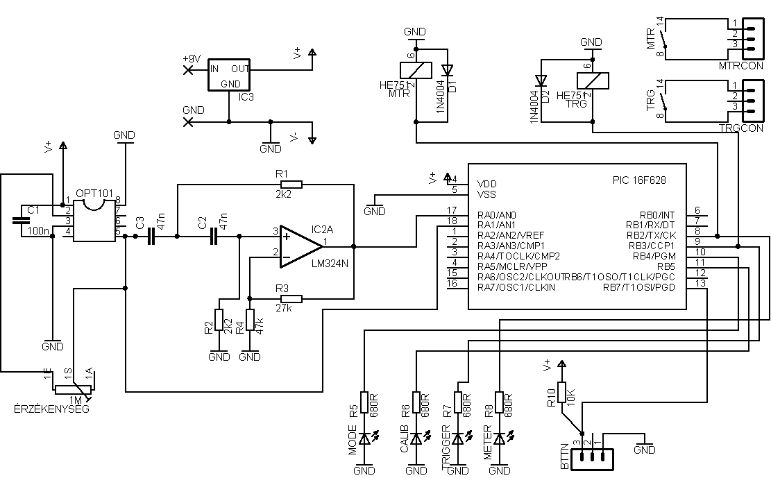
From what I understand the micro gets it’s input on lines 17 and also 18. Line 18 is the signal straight from the light sensor while the signal to pin 17 comes from a high pass filter that only triggers on fast light changes. When the PIC sees a ‘flash’ it triggers the camera through pin 9.
Here is the assembler code:
	LIST	p=16F628
	include "P16F628.inc"
	ERRORLEVEL	0,	-302
	__config 0x3F18


		cblock	0x20			;start of general purpose registers
            Cz1,Cz2,Cz3
			hold			;Comparator pervious state
  		    count			;used in looping routines
			count1			;used in delay routine
			counta			;used in delay routine
			countb			;used in delay routine
			tmp1			;temporary storage
			tmp2
			templcd			;temp store for 4 bit mode
			templcd2

			Value				; Value to be sent to LEDs
			Dirty				; Is LCD display dirty?
			Digit0				; First digit for display
			Digit1				; Second digit for display
			Digit2				; Third digit for display
			DigitIndex			; Digit pointer
			J					; 101us delay outer loop counter
			K					; 101us delay inner loop counter
			L					; 4.1ms delay outer loop counter
			M					; 4.1ms delay inner loop counter

		endc

LCD_PORT	Equ	PORTB
LCD_TRIS	Equ	TRISB
LCD_RS		Equ	0x00			;LCD handshake lines RS PORTB RB0
LCD_RW		Equ	0x01			;RW PORTB RB1
LCD_E		Equ	0x02			;E PORTB RB2


C1OUTMASK   	Equ b'01000000'		;Comparator1 output bit
C2OUTMASK	        Equ b'10000000'		;Comparator2 output bit

SW1		Equ 7				;RB7 (pin 13)
TRIGGER     	Equ 3				;RB3
METERING    	Equ 2				;RB2
LED_CAL		Equ 5				;RB5
LED_MODE	Equ 4				;RB4
		org	0x0000

;Chip funkciok inicializaslasa

      		clrf PORTA
      		clrf PORTB

		movlw 0x32       ;Internal voltage reference mode CM<2:0>=010
	 	movwf	CMCON


SetPorts
        	bsf 	STATUS,	RP0	;select bank 1
		movlw	b'10000000'	;RB7 input RB6-0 input
		movwf	PORTB		;PORTB - Mind a 8 vezetek
		movlw   0x07
        	movwf   TRISA		; RA<2:0> Input RS<4:3> output

		bcf 	STATUS,	RP0	;select bank 0


;startup
calibrate1

;time to settle down
				bsf  PORTB, LED_MODE
				bcf  PORTB, LED_CAL
				call Delay250ms
				bcf  PORTB, LED_MODE
				bsf  PORTB, LED_CAL
                call Delay50ms
				bsf  PORTB, LED_MODE
				bcf  PORTB, LED_CAL
				call Delay250ms
				bcf  PORTB, LED_MODE
				bsf  PORTB, LED_CAL
                call Delay50ms
				bsf  PORTB, LED_MODE
				bcf  PORTB, LED_CAL
				call Delay250ms
				bcf  PORTB, LED_MODE
				bsf  PORTB, LED_CAL
                call Delay50ms
				bsf  PORTB, LED_MODE
				bcf  PORTB, LED_CAL
				call Delay250ms
				bcf  PORTB, LED_MODE
				bsf  PORTB, LED_CAL
                call Delay50ms
				bsf  PORTB, LED_MODE
				bcf  PORTB, LED_CAL
				call Delay250ms
				bcf  PORTB, LED_MODE
				bsf  PORTB, LED_CAL
                call Delay50ms
				bsf  PORTB, LED_MODE
				bcf  PORTB, LED_CAL
				call Delay250ms
				bcf  PORTB, LED_MODE
				bsf  PORTB, LED_CAL
                call Delay50ms


calibrate			call vrset1041V
				bcf  PORTB, LED_MODE		;Mode led 0


comploop0			bcf   PORTB, LED_CAL
				bsf   PORTB, LED_MODE
comploop1
				btfss PORTB, SW1
				goto mode_select_switch

				movf CMCON,w
				andlw C2OUTMASK			;1 az output bit ?
				btfsc STATUS,Z
		        	goto comploop0

				bsf PORTB,LED_CAL
                		bcf PORTB,LED_MODE
				goto comploop1


mode_select_switch
				Call Delay250ms

				Call vrset0625V

				bsf PORTB, LED_MODE		;mode led on
				bcf PORTB, LED_CAL		;calibrate led off
				Call Delay250ms
				bsf PORTB, LED_MODE		;mode led on
				bcf PORTB, LED_CAL		;calibrate led off
				bcf PORTB, TRIGGER
				bsf PORTB, METERING


Triggerloop 	btfss PORTB, SW1
				goto exit_trigger_mode

				movf CMCON,w
				andlw C1OUTMASK			;1 az output bit ?
				btfsc STATUS,Z
		        	goto Triggerloop

       ;Trigger !!

				bsf PORTB, TRIGGER
				call Delay250ms
				call Delay250ms
				bcf  PORTB, TRIGGER
				call Delay50ms
				bcf  PORTB, METERING
				; villog

				bcf  PORTB, LED_MODE
				bsf  PORTB, LED_CAL
				call Delay250ms
				bsf  PORTB, LED_MODE
                		bcf  PORTB, LED_CAL
				call Delay250ms
				bcf  PORTB, LED_MODE
				bsf  PORTB, LED_CAL
				call Delay250ms
				bsf  PORTB, LED_MODE
                		bcf  PORTB, LED_CAL
				call Delay250ms
				bcf  PORTB, LED_MODE
				bsf  PORTB, LED_CAL
				call Delay250ms
				bsf  PORTB, LED_MODE
		                bcf  PORTB, LED_CAL
				call Delay250ms
				bcf  PORTB, LED_MODE
				bsf  PORTB, LED_CAL
				call Delay250ms
				bsf  PORTB, LED_MODE
                		bcf  PORTB, LED_CAL
				call Delay250ms
				bcf  PORTB, LED_MODE
				bsf  PORTB, LED_CAL
				call Delay250ms
				bsf  PORTB, LED_MODE
                		bcf  PORTB, LED_CAL
				call Delay250ms
				bcf  PORTB, LED_MODE
				bsf  PORTB, LED_CAL
				call Delay250ms
				bsf  PORTB, LED_MODE
                		bcf  PORTB, LED_CAL
				call Delay250ms
				bcf  PORTB, LED_MODE
				bsf  PORTB, LED_CAL
				call Delay250ms
				bsf  PORTB, LED_MODE
                		bcf  PORTB, LED_CAL
				call Delay250ms
				bcf  PORTB, LED_MODE
				bsf  PORTB, LED_CAL
				call Delay250ms
				bsf  PORTB, LED_MODE
                		bcf  PORTB, LED_CAL
				bsf  PORTB, METERING

		        	goto Triggerloop

exit_trigger_mode

				Call Delay250ms
				bcf PORTB,LED_MODE
				bcf PORTB,METERING
				goto calibrate1


;Set VREF to 1.041V
vrset1041V
		bsf 	STATUS, RP0			;select bank1
		movlw	0xE5				;1.041V (for check gain)
		movwf	VRCON
		bcf		STATUS,	RP0
        	call	Delay250ms			;Time to settle down VREF
		return

;Set VREF to 0.625V
vrset0625V
		bsf 	STATUS, RP0			;select bank1
		movlw	0xE3				;0.625V (for check gain)
		movwf	VRCON
		bcf		STATUS,	RP0
        	call	Delay250ms			;Time to settle down VREF
		return


Delay250ms			movlw	d'250'			;delay 250 ms (4 MHz clock)
				movwf	count1
d1A				movlw	0xC7
				movwf	counta
				movlw	0x01
				movwf	countb
Delay_0A
				decfsz	counta, f
				goto	$+2
				decfsz	countb, f
				goto	Delay_0A

				decfsz	count1	,f
				goto	d1A
				retlw	0x00


Delay50ms		movlw	d'100'			;delay 50 ms (4 MHz clock)
				movwf	count1
d1B				movlw	0xC7
				movwf	counta
				movlw	0x01
				movwf	countb
Delay_0B
				decfsz	counta, f
				goto	$+2
				decfsz	countb, f
				goto	Delay_0B

				decfsz	count1	,f
				goto	d1B
				retlw	0x00
		end
My questions are:
- What is going on in the ‘calibrate’ function?
- How does the micro detect a lightning flash? Is it using the input on line 17? Or line 18? Is it comparing 17 to 18? Something else?
If anyone could help me make any sense of the assembler code I would be very grateful! I'm also including the circuit schematic so you can get a better idea of what going on.