Grumpy_Mike:
It is. It is like a miniature taser, sparks and everything. You apply it to the outside of a box at everything you can see sticking out. So that is socket ends on all connectors, plugs and even through ventilation holes and slots. The box under test is on a table standing on a huge sheet of aluminium, surrounded by a large space, barriers and traffic cones, and warning signs.
Wawa:
400:1 means you're measuring >1000volt?
Give us the full picture.
Forget about zener diodes.
You could use a 2-stage voltage divider, and clamp to the unregulated supply (5volt, 12volt) of that 3.3volt processor, with normal diodes. That would take care of positive spikes, negative voltage, even when the Arduino is off (unlike a zener).
Leo..
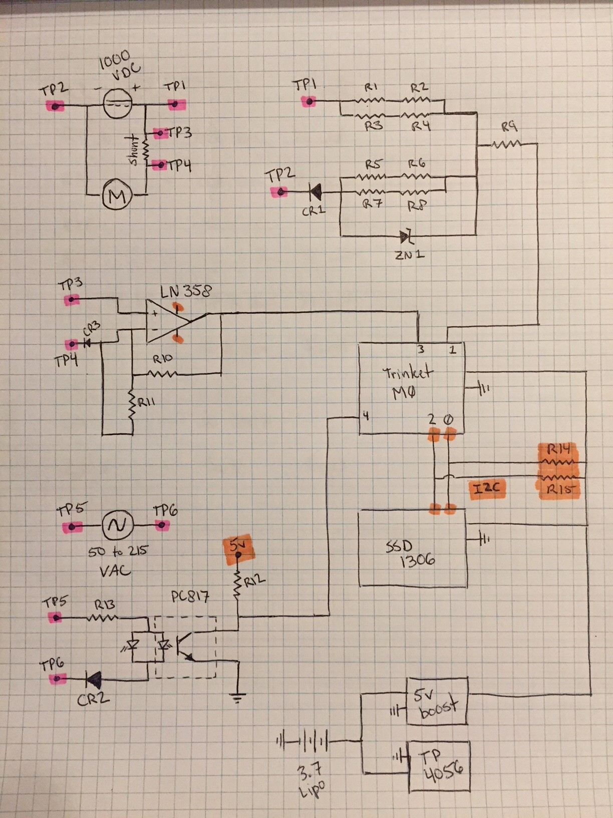
I'm building a plug in horse power calculator for a 600 vdc system. R1 in the voltage divider is 10M ohms and R2 is 26k ohms.
sorry I was late to respond. I've been busy at work. I will post a full schematic and all component information ASAP.
More than 10,000volt is needed to reach 1mA pin fault current with a 10Megohm resistor.
Don't worry about protecting the pin from that.
What is important is that that 10Megohm resistor.
Flash-over is a greater danger, so it needs to be able to handle several Kv.
You can buy high-voltage resistors, but they are easily made from a string of lower value resistors inside a piece of heatshrink. A 10-string of 1Meg resistors could work.
Don't forget a (10-100n) cap between pin and ground.
That not only helps the A/D during sampling, but also kills spikes.
Leo..
I'm actually using four 10M resistors in series parallel. The math with just one resistor put me at 1/8 watt. All the resistors I'm for that circuit are 1/4 watt rated.
I'm at work now. I will make it a point to give specifics when I get home.
Seems you're overthink things.
1200volt across 10Meg is 0.144watt. Perfectly fine for a 1/4watt resistor.
As said, the only worry is flashover.
The R5-8 with zener and diode setup doesn't make sense.
It should be a single resistor to Trinket ground (with smoothing cap across).
That resistor should max have the Trinket's internal reference across (~2.23volt?), so dissipates virtually nothing.
The opto circuit is not correct.
An indicator LED (Vf ~2volt) across an opto LED (Vf ~1.25volt) won't light up.
Should connect both LEDs in series, and one diode across both LEDs (for AC).
Not sure why you use 10Amp diodes there. A 100mA 1N4148 is big enough for this. 1N4004 if you must.
I'm sure an L358 won't be happy with 1000volt on it's inputs...
Better use some clip-on hall sensor there.
+1 for the neatly drawn diagram though.
Leo..
Edit: A trinket has a 3.3volt processor, so I2C pull up should go to 3.3volt, not to 5volt.
Wawa:
I'm sure an L358 won't be happy with 1000volt on it's inputs...
Better use some clip-on hall sensor there.
+1 for the neatly drawn diagram though.
Leo..
Edit: A trinket has a 3.3volt processor, so I2C pull up should go to 3.3volt, not to 5volt.
yes I failed to put that the orange would be 3.3 instead of 5... The L358 isnt seeing 1000 volts its on a shunt resistor and should be around 75mV max at normal conditions.
and for the CR1 and CR2 i was aiming for safety
LandonW:
The L358 isnt seeing 1000 volts its on a shunt resistor and should be around 75mV max at normal conditions.
and for the CR1 and CR2 i was aiming for safety
Might be <=75mV between the inputs, but your diagram shown them connected to the +side of the motor.
Opamp inputs shouldn't normally have more than the supply voltage of the opamp on them.
Understood, but not needed, and creating more problems.
Forgot to add that R9 also must go, and R2 also must connect to 3.3volt.
R2 can actually be removed if the Trinket has internal pull up enabled.
Leo..
Wawa:
Might be <=75mV between the inputs, but your diagram shown them connected to the +side of the motor.
Opamp inputs shouldn't normally have more than the supply voltage of the opamp on them.
Understood, but not needed, and creating more problems.
Forgot to add that R9 also must go, and R2 also must connect to 3.3volt.
R2 can actually be removed if the Trinket has internal pull up enabled.
Leo..
ok, i see what your saying now.... the shut math is 1mV = 75 amps.
how would you suggest that i get the amp reading for my calculations??
this is my first attempt at high voltage project....
if you could find the time to draw a schematic that you would use i would appreciate it.
this project is for a EMD 40 -2 locomotive. the AC circuit is for RPM sensing
The main gen of this locomotive has an alternator in the same housing. this gen has no need to maintain Hz. its basically more RPM = more power.
question about the opAmp…. since the opAmp isn't connected at + and - the potential difference isn't 1000vdc? since the potential difference between the shunt is indeed smaller than the potential difference on the supply
A shunt (galvanic connection) will only work of shunt voltage is within the supply range of the opamp,
although some chips can measure somewhat outside that range.
So not a big problem if the shunt was in the ground wire of the motor, but impossible on the +600volt side.
I remember you once posted that the shunt was part of the instruments of the loc.
Not sure how to solve it, but a clip-on DC hall sensor (on any of the motor wires) could work.
You might not even need the opamp for that.
Leo..
Wawa:
A shunt (galvanic connection) will only work of shunt voltage is within the supply range of the opamp,
although some chips can measure somewhat outside that range.
So not a big problem if the shunt was in the ground wire of the motor, but impossible on the +600volt side.
I remember you once posted that the shunt was part of the instruments of the loc.
Not sure how to solve it, but a clip-on DC hall sensor (on any of the motor wires) could work.
You might not even need the opamp for that.
Leo..
yes this has been an on again and off again project.
the normal procedure for finding the horse power with these test points is voltage between TP1 and TP2 which is usually around 600vdc, Then take a voltage reading at TP3 and TP4. (it will show in mV)
I guess i need some education on why it would be 600+ volts for the OpAmp and not for a DMM??
Im half tempted to "go for smoke"
If you're going to use the Trinket high-side (near the 600volt supply), then you can't measure voltage.
Current will also be a problem, because you also have to power the Trinket high-side.
I would forget about that loc shunt for the Trinket (only use it for your DMM).
Much better/safer to keep the Trinket grounded to the loc, and use a clip-on or pass-through hall sensor based DC current sensor with 4-20mA output.
And the string of resistors I recommended for voltage.
What sort of current are we actually talking about (Amps), and is it bi-directional (loc forward/reverse)
Leo..