im trying to design a way to prevent over voltage of a 5v analog INPUT. i cant go over 6-7v MAX.
I designed this circuit below. Would this protect ADC IN from the "V2 120v overvoltage"? "D2/Z1.." should clamp at 5.6V and D3 should prevent 120v from going back to the 5v line? i think my resistors being 1/4watt should protect the diode from over current?
Any advice about creating this circuit would be greatly appreciated.
I am a little concerned with D3. I'm not sure what type/value of diode to use. I was thinking about using TVS "P6KE6.8CA-E3/54" Its a 6.8v 600w TVS. but would this work for protecting 120v from travelling back to "V1 5V"?
I dont need the whole 0-5v analog range. i also dont want to cook any resistors..
EDIT: i realize tvs diode i mention is actually bidirectional and most likely wont perform well in that configuration. not sure what to do about protecting V1 from V2
I initially thought about using Schottky diodes instead of Zener's but I didn't find any with a voltage less than 12v?!? that's when i saw the large selection for Zener's. My input voltage to ADC IN would be about 5.2V and the main power rail is 5.4V. I had no success finding 6v/5.6/5.2 Schottky diodes.
I'm still learning about diodes. Can you help me choose one?
When you say this,
Quite a difference if the processor is unpowered (VCC = 0volt).
do you mean what happens if the circuit is unpowered but somehow 120v becomes latched to the ADC IN circuit?
Why the low resistor values.
I thought the R2 1k would be sufficient to protect ADC IN from over current and that R1 100ohm may be unnecessary?
EDIT: im not sure, so i will ask.. What exactly would happen if Vcc was 0V/unpowered and i apply 5V to ADC IN. the spec sheet for my pcf8591 says, ADC MAX Input V = Vcc+ 0.5volt.
Between R2 and R3 'ignoring the diode and V2" would be a conducting moisture sensor. its some copper tape and paper.
the V2 is there to show the scenario if the water detected had been energized by 120V mains ac power. I think V2 is expressed as DC in the schematic.
I would like to protect the 5V rail and ADC IN from voltage leaking from some 120vac source into the conductive moisture sensor wires and into the 5v circuits and ADC IN.
Diodes usually have a high (reverse) voltage rating. This is a max. rating. The exact value is usually not relevant. You will destroy the diode if you go over it.
Zeners have a well defined (reverse) voltage. You can use this to make a constant voltage. That is why you can buy them for a wide range of voltages (like 3V3 4V7 5V6 etc.).
Schotky diodes have lower forward voltage drop than silicon diodes. In this case that is handy because the silicon diode will start protecting your input pin when the max is already reached (Vcc + 0.6V). The Schotky will act before that point.
How would i use the Schottky diode on ADC IN. if im sending 5v to ADC IN then the diode will have to let voltage/current flow to ADC IN. how could i use it to protect ADC IN from higher voltages.
I know tvs starts conducting when it reaches breakdown voltages but if i use a 200v Schottky it would just let the power through to ADC IN?
I strongly suggest availing yourself of some industry design resources on this subject. It's what I did. Start by looking at app notes for TVS.
You've presented the question in such a hypothetical way that it's hard to advise. For example, if the 120V source lasts for any significant interval, a TVS/diode circuit won't be enough as it will burn up.
That is why i thought about using the Zener and some resistors. R2 would limit the current Z1 would see. this would be within spec of the diode, so this should be okay? Im not certain what it takes to turn the resistor into a glow stick.
but this leaves me with the problem with D3 and V2 traveling up the " V1 5V line". I would much rather change the diodes/resistors on these ADC IN's rather than everything else behind it. also im going to have around 20 of these ADC INPUTS to protect..
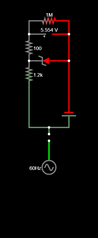
I ran out of time for the simulator i was using, now im using falstad. In this circuit the Zener is 5.6v and the diode is a schottky 200v diode. However it still shows the whole circuit going to -120v ac at 60hz speed.
The ac voltage is set to 120vac. The dc voltage is set to 6.6V the voltmeter dont show any change but the circuit fades red to green when 120vac is connected?
EDIT: I hope this could work. i dont really know what im doing. i guess ill try this unless anyone has any objections. I have to wait for my diodes to arrive.
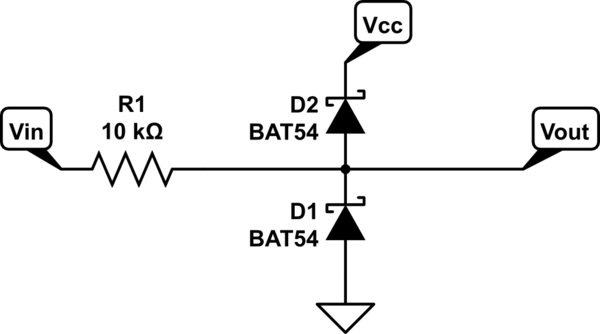
Seems you do not understand how to use them. The Schottkys go from the ADC pin to the Vcc and from the ADC pin to ground so that they conduct whenever the voltage goes 300 mV outside these limits. If the microcontroller is unpowered, then Vcc and ground are the same and the diodes conduct whenever the voltage goes 300 mV above or below ground.
Don't know what "latched" means, but the resistor between the 120 V input and the ADC input will limit the current in the diode, which means that you do not want it to be more than a few mA. 120 V over 10 mA is 12k and 1.2 Watts dissipation in the resistor. Any lower resistance will mean more current (Schottkys will generally take at least 100 mA) and more dissipation in the resistor, so you probably want to use something more like 47k, ½W.
The only place where you could use a zener is across the supply of the Arduino, in case the clamping diodes dump more current on the 5volt rail than the Arduino normally draws.
But then I would use a TVS diode (super-zener) with a stand-off of 5volt.
Leo..
I must still be misunderstanding something. I thought that if the diode was bi directional that voltage/current could flow from cathode-anode || anode-cathode. I understand that Schottky has low forward voltage drop.
Could you give me a part number for a diode i could read the datasheet. it could hep me make more sense of what im doing. at minimum im still not sure what voltage diode to use.
EDIT: im not sure if you intended for me to loot at the bat54 in your schematic or not. i would prefer through hole components
In this circuit i made. it should flow on one schottky but not the other? is the simulator right? im worried i may be wasting my time with falstad
Your diagram (post#13) doesn't make sense.
The cathode of the clamping diode on the left goes to Arduino's 5volt supply, not the 120volt supply. That diode prevents getting more than VCC+0.3volt (5.3volt) on the analogue pin.
And what is that 4.986volt doing there. Is it a supply, or the measurement result.
Do you understand that if you put 120volt through any value resistor on the analogue pin, then the voltage on the Arduino pin will always be 5.5volt.
Please use drawing conventions.
Supply on top, ground at the bottom, inputs left, outputs right.
Leo..
Basic Ohms law stuff.
An Arduino pin has an extreme high impedance (draws no current).
Zero current through a resistor = no voltage across the resistor (same voltage on the other side).
You can only measure a resistor if you draw current through it (make the sense resistor part of a voltage divider).
Now i need to protect this from 120vac if 120vac leaking into water and Moisture Sense wires. The bat54 is a diode array, it looks like 3 pin surface mount component. does that mean that all i need is to connect vcc & gnd to a single bat54?
But d2 would allow 5v to ADC IN? this would not work.
also d1 would create a path to gnd.
A little off subject but, if 120v were to leak into the circuit and bring voltage "limited" to 5v to ADC IN this would be okay, if the circuit could handle it for a few seconds this would be enough time to read the input, notice the high input then turn off the power source. if not, then it burns up. but at least there could be a chance to save the circuits
The perfect scenario would be a circuit that dont generate too much heat from power dissipation of the resistor and diodes but still keep the voltages within the right voltage range.
In a no leak situation there adc is pulled low, by pulldown resistor, so if 5v or anything greater than 1v showed up to ADC IN, the MCU "should/could" disable the 120vpower. if power is not disconnected and the circuit can handle it and not burn up, then that is ideal.