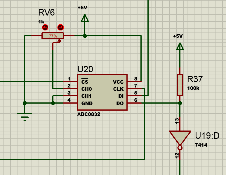
I am trying to write some data to a (serial in/serial out) ADC0832 IC.
I managed to make an electronic circuit that works fine in Proteus simulator.
But now I am trying the arduino way. Also the PIC MCU after arduino.
The problem I face is [different timing].

From what I can observe, this chip does not like delays in it's DI (Diginal In) pin 5.
I managed to make 2 solutions in arduino, that both worked:
void setup()
{
 Serial.begin(9600);
  while (!Serial) {}  // wait for serial port to connect. Needed for native USB port only
  pinMode(13, OUTPUT);
  pinMode(12, OUTPUT);
}
byte x = 0b0110;

void loop()
{
    //signal
    digitalWrite(13, x);
    digitalWrite(13, LOW); //doesnt work without this line - weird

      /*
this solution worked as well
      digitalWrite(13, LOW);
      digitalWrite(13, HIGH);
      digitalWrite(13, HIGH);
      digitalWrite(13, LOW);
     */
}
So this code worked fine.
You can observe NO DELAYS in the loop method. Because the ADC does not like it at all.
So simple and direct stream of data, ok?
Now... in [all electronic] circuit (not the arduino cct), I also have a clock cct and a Hold cct. The clock is clocking the electronic cct that is generating the DI code and the ADC0832 clock pin 7. The Hold cct, is holding the Output result after the display cct that is getting its data from DO(Digital Out) pin 6. If the Hold cct is not added, the display cct will shift everything to 00000000 output.
The hold code is quite simple.
void Reset()
{
     //Reset
    digitalWrite(12, LOW);
    digitalWrite(12, HIGH);
    delay(10);
}
As you can observe I put it on a separate pin12 this one.
I also put a clock pulse on pin 11.
None worked. Because "NO DELAYs" in the stream for pin 13 !!!
What I did and worked so far, was to add a separate clock cct, to clock from hardware, and also a Hold cct also as a hardware module.
I want all these 3 "timing elements" done in software - in code, from the arduino pins only. To liberate the hardware modules I've added so far.
So 3 specialized [Loop] that can hold specific code in them. Not a single [Loop] as it is now.
Ask me anything what you didnt understand and I will clarify.
Thank you so much for reading.
~q12~