Apologies for what might seem like such a basic question. My project is going over the amp draw limit of the Arduino, I can see this with some weird behaviour from my 7segment display and readings that I am getting on one of the analog pins when reading button inputs (constantly fluctuating between 0 and 16). I need to add an external power supply and I have been searching for a couple of hours now on how to add one aswell as the components needed.
My current project is using;
Arduino Nano
8 digit 7 segment display (running on max7219) - Soon to be extended to include another 8 segment display
6 LEDs
1 10LED light bar (all 16 LEDs running off of 2x74HC595's)
13 momentary buttons (split across 2 analog pins using resistors to read which is pressed)
I'm trying to learn the electronics whilst building this project, I started with an Arduino kit that had a load of components and walked through tutorials, but now my custom project is more ambitious than those, I can't find anything on adding a power supply. I know I can't just run a USB pack that has more amps through the Arduino or plug something into the VIN pin, it would need to handle to VCC and GND pins of the components directly I assume.
Any links to some guides you know of or videos would be appreciated!
Notwithstanding confusion engendered by the tutorials and references on the Arduino site (and others), you should not be using "Vin" in any way for any meaningful project. You have not actually explained what you are doing so far.
To power a proper project, you use a proper 5 V power supply - for up to its rating, a readily available USB "phone charger" is usually very convenient.
You connect the 5 V to all the 5 V devices and to the "5V" pin on the Nano. While it might be easy with a cable, connecting the "Phone charger" to the USB port means that there is a diode between that and the "5V" pin which loses some significant voltage and is limited to a 500 mA rating.
I am building a health tracker for Dungeons and Dragons, so it will contain 7 segment displays for health, temporary health, level counter, spells slots (in total this will require ~15 digits), then I have 6 LEDS, a 10 LED light bar, and 13 momentary buttons with different resistors (5 to one analog pin, and 8 to another) which read the user input and adjust LEDs being on/off and the values in the 7 segment display.
For now, I am using serial monitor to read what should be displayed on the 7 segment displays, as I do not want to overdraw power from the arduino. I am currently just powering this either through the USB or from a 9v battery with VIN for breadboard build and testing.
When I convert this from test board to final version, I will need a better power source than the arduino board itself I believe, as the current draw will be too much for the nano. I want this to be battery operated, so at the gaming table we do not have cables out.
I am happy to buy a power regulator board, or power supply module as well as compatible battery. I am just struggling to find information that could help my use case, which I wouldn't have thought would be niche! I'm very happy to read, research and learn, I just need as pointer in the right direction.
Paul, to clarify the quoted part, I saw a youtube video that said to ignore the 5v and GND of the nano board for the components being battery powered so that they all share the circuit from the battery. And this is where I struggle as I see conflicting information, another example is with adding a capacitor to the shift registers, some say add it to the data pin, others say to put it over VCC and GND (the latter I thought was correct) but this is another topic I won't go into in this thread.
ok, I'll see if I can put one together. Fritzing used to be free, but I don't have that anymore so I'll have to find some other software that will let me do it (I don't think I can deal with Paint!)
No doubt, which is why I mentioned the confusing tutorials and references on the Arduino site (and others).
I can only advise - you are doing a serious project - do not use "Vin" in any way. It is basically useless.
For a few LED displays, you provide 5 V, nothing else. If you must operate on batteries, I do suggest four NiMH "AA"s in a holder to provide 5 V. It would probably also work from three alkaline AAs at 4.5 V which is within the specification of the MAX7219. When you do not require the USB interface, a Pro Mini saves a little current (and can be made to sleep).
Might as well!
Putting a capacitor on the data pin simply relates to a quite stupid mistake that appeared on the Arduino site itself and was only partially corrected when repeatedly pointed out. Which is an example of why I warn to get your information here rather than elsewhere, even Arduino site tutorials!
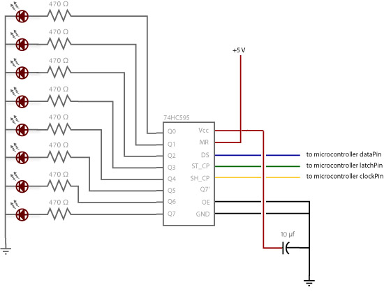
Note this diagram was corrected (sort of!):
Generally the bypass capacitor directly across the 74HC595 supply pins is 100 nF. The MAX7219 also requires its own but a 10 µF is advised in addition.
But this breadboard diagram and all following
continue to show the (100 nF then) capacitor wrongly connected to the latch pin.
So it need not be surprising to find other ignorant people suggesting all sorts of stupid things.
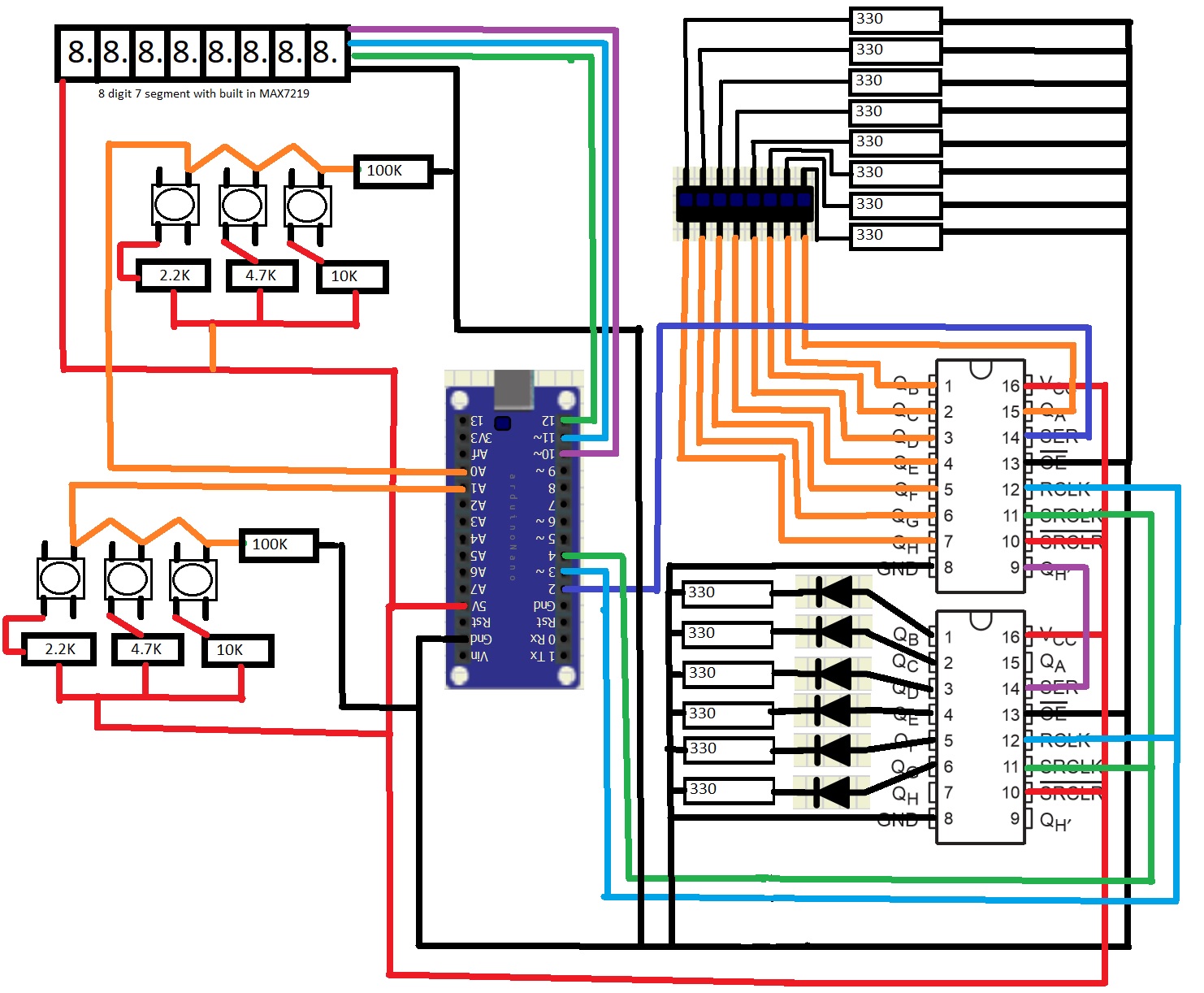
Thanks Paul, I'm in a meeting at the moment but will have a read through of your information shortly. I have uploaded a diagram to the best of my abilities at the moment, I do have an additional 8 buttons following the same format but connected to pin A1. I also have several MAX7219's turn up today that will be driving the seperate 7 segment displays, the 8 digit display is on a premade board with a 7219 IC. It is the premade displays that I have up and running but with some odd issues (which I assume is due to power delivery)
Sorry, do you mean you're not sure what I'm saying, or you understand but it's complete nonsense? On the "tutorial" he was saying just don't use 5v out or GND from Arduino, instead use the + and - from the battery for all components, "it's as easy as that" he says. And apparently that's how you wire up a battery to the circuit, which providing it's a 5v source, it will give the necessary amps to drive the circuit.
That's my bad regarding VIN, I thought that was an alternative to using the barrel jack to power the Arduino if you're using an external supply for the 5v and GND of other components (which is on the basis of using 5v from the battery not from the 5v pin on Arduino).
Hi,
Please review your diagram in post #9.
Where are the power supply wires.
Where are the gnd wires?
All your components that have gnd connections need to be connected together, including the 595, and the Nano.
What is Vin connected to?
Look at the analog switch circuit you have drawn, it cannot work like that.
No matter what button you push, 5V will be devidered to A0.
Please draw your complete circuit, include your power supply and it connection, include component labels, your 595 seem to have no Vcc or gnd pins.
Forget CAD and use a pen(cil) and paper, then send an image.
yes, I have a 5v connection going into each of the 595's, and a GND coming out also. These are all connected and both using the 5v pin and GND pin respectively.
The switch diagram isn't exactly how it is on the board, but hopefully the concept is appreciated, where pressing a button will adjust the resistance allowing me to know which button has been pressed by reading on the analog pin (the software I used didn't have a button with 4 posts).
Currently I am not using VIN for anything, I have connected a 9v battery to it on occasion to see if that would power the LEDs and work normally, however I am mostly using the usb connector for power whilst building this.
I appreciate that an accurate diagram will help in driving a solution, but for a general "how do I add a battery for power" or even assistance in a tutorial to learn best practice myself how to do this, would it be necessary? From everything I have seen so far, what I am trying to drive off of the Arduino is too much for the pins. If not, then the issue I need to resolve is with my fluctating readings that aren't 0 on the analog pins when the 7 segment display is added (but works perfectly fine without it)
I have added a more accurate complete diagram, with a couple of caveats, I will eventually have 2 of the 7 segment displays, and there are actually a total of 13 buttons (8 on pin A1, and 5 on pin A0).