adding delays to the "on" of L1 doesn't work. When I modify the blink code so that an additional 2 lines state the same delay of 1 second, it does nothing to the arduino board light and there are no errors. I just got the Mega kit. What am I doing wrong?

Oops.
Could you please share the code you're running, in modified form?
Here' the code:
// the loop function runs over and over again forever
void loop() {
digitalWrite(LED_BUILTIN, HIGH); // turn the LED on (HIGH is the voltage level)
delay(1000); // wait for a second
delay(1000);
delay(1000);
digitalWrite(LED_BUILTIN, LOW); // turn the LED off by making the voltage LOW
delay(1000); // wait for a second
Please share the complete code.
Also please use code tags

Did you in fact upload/program the new sketch to the board?
Posting a picture and schematic of your setup will help. This is assuming you are using an external LED.
What is that? Does it have an Arduino with an Intel processor? Please post a link.
the Mega kit is from Elegoo and is called Mega 2560.
Jim
here's the complete code which I have saved as Myblink
This example code is in the public domain.
https://www.arduino.cc/en/Tutorial/BuiltInExamples/Blink
*/
// the setup function runs once when you press reset or power the board
void setup() {
// initialize digital pin LED_BUILTIN as an output.
pinMode(LED_BUILTIN, OUTPUT);
}
// the loop function runs over and over again forever
void loop() {
digitalWrite(LED_BUILTIN, HIGH); // turn the LED on (HIGH is the voltage level)
delay(1000); // wait for a second
delay(1000);
delay(1000);
digitalWrite(LED_BUILTIN, LOW); // turn the LED off by making the voltage LOW
delay(1000); // wait for a second
}
Jim
I think I uploaded my program as Myblink. How can I make sure I did?
Jim
How can I include a screen image to the forum?
Jim
Are you sure you're not confusing saving a project with uploading to the arduino board? Programming the board doesn't involve any project names.
Maybe I am confusing saving and uploading. How do I tell and how do I do both?
Sorry, formerly Fortran programmer.
Jim
Topic moved to a more suitable location on the forum.
You don't state which version of the IDE. Below screenshot is for IDE 2.x; in IDE 1.x the right icon is not available.

The left button is to compile your code; Arduino calls it Verify. The middle button (in the screenshot) is for upload; upload does involve a compile as well.
Regarding saving, you can look under file/preferences in the IDE
.
If you remove the tick from the marked entry your code will not automatically be save. Due to a bug in IDE 2.x (I think actually one of the underlying tools) I would leave the entry ticked as a beginner.
Thanks. I have been using the check mark icon to compile and the right arrow to compile and upload. I can compile without an error, but when I click on the right arrow that is when I get an upload error that says "An error occurred while uploading the sketch". While googling this it says to check for a problem with the cable and to not use a USB expander. I am using an all-in-one computer and I don't have a port directly on the computer I can use. I'll try removing the cable between the computer and the USB expander so I have a port I can plug into if that doesn't work I'll try ordering a new cable. Thanks much for the help.
Jim
So no surprise that your code does not have an effect on the LED behaviour 
Please disable verbose output during compilation and enable verbose output during upload under file/preferences. Upload the sketch and post the complete output here using code tags.
You have selected a port in the IDE; does that port disappear when you disconnect the board? Does it disappear from your operating system when you disconnect the board?
I could not find which operating system you are using; please mention it.
The com port changes on the IDE when I disconnect the cable: the port changes from "Com4 (Arduino...) to just Com4.
When I look at com ports in Device Manager the port disappears when I disconnect the cable.
The port is as expected when I connect the cable.
I am using windows 11 64 bit.
I have disabled verbose output for compilation and enabled it for upload.
Here's the complete Sketch with delays set to 500 milliseconds. The sketch name is Myblink.
/*
Blink
Turns an LED on for one second, then off for one second, repeatedly.
Most Arduinos have an on-board LED you can control. On the UNO, MEGA and ZERO
it is attached to digital pin 13, on MKR1000 on pin 6. LED_BUILTIN is set to
the correct LED pin independent of which board is used.
If you want to know what pin the on-board LED is connected to on your Arduino
model, check the Technical Specs of your board at:
https://www.arduino.cc/en/Main/Products
modified 8 May 2014
by Scott Fitzgerald
modified 2 Sep 2016
by Arturo Guadalupi
modified 8 Sep 2016
by Colby Newman
This example code is in the public domain.
https://www.arduino.cc/en/Tutorial/BuiltInExamples/Blink
*/
// the setup function runs once when you press reset or power the board
void setup() {
// initialize digital pin LED_BUILTIN as an output.
pinMode(LED_BUILTIN, OUTPUT);
}
// the loop function runs over and over again forever
void loop() {
digitalWrite(LED_BUILTIN, HIGH); // turn the LED on (HIGH is the voltage level)
delay(500); // wait for a second
digitalWrite(LED_BUILTIN, LOW); // turn the LED off by making the voltage LOW
delay(500); // wait for a second
}
Here's the output:
Arduino: 1.8.18 (Windows 10), Board: "Arduino Mega or Mega 2560, ATmega2560 (Mega 2560)"
Sketch uses 1536 bytes (0%) of program storage space. Maximum is 253952 bytes.
Global variables use 9 bytes (0%) of dynamic memory, leaving 8183 bytes for local variables. Maximum is 8192 bytes.
C:\Users\techn\AppData\Local\Arduino15\packages\arduino\tools\avrdude\6.3.0-arduino17/bin/avrdude -CC:\Users\techn\AppData\Local\Arduino15\packages\arduino\tools\avrdude\6.3.0-arduino17/etc/avrdude.conf -v -patmega2560 -cwiring -PCOM4 -b115200 -D -Uflash:w:C:\Users\techn\AppData\Local\Temp\arduino_build_373519/MyBlink.ino.hex:i
avrdude: Version 6.3-20190619
Copyright (c) 2000-2005 Brian Dean, http://www.bdmicro.com/
Copyright (c) 2007-2014 Joerg Wunsch
System wide configuration file is "C:\Users\techn\AppData\Local\Arduino15\packages\arduino\tools\avrdude\6.3.0-arduino17/etc/avrdude.conf"
Using Port : COM4
Using Programmer : wiring
Overriding Baud Rate : 115200
An error occurred while uploading the sketch
This report would have more information with
"Show verbose output during compilation"
option enabled in File -> Preferences.
That's a good sign.
In the Arduino IDE, there's a 'serial monitor' at the bottom of the screen. Try closing it. Sometimes, this serial monitor can block access to the COM port.
I suspect that you have some form of conflict. Now the question is what COM4 is?
Maybe it can be determined using the following steps.
- Disconnect the Mega
- In Windows device manager, right click on COM4 and click Properties.
- Click the Details tab.
- In the Property drop down, select Hardware Ids
For a connected Mega it will show something like below
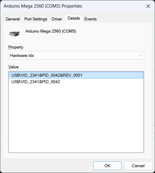
The VID is 2341 and the PID is 0042; this indicates that this is a Mega with an Atmel 16U2 serial-to-usb converter.
What does COM4 show for your disconnected Mega?
there is 1 port listed in device manager as (Arduino Mega 2560 (Com4)). That's all that is shown i.e. no VID
I just noticed another item listed under ports for com4 is says "standard serial over bluetooth link (com4)
When the Arduino is unplugged, there is no port listed for it in device manager. If Plug it in the arduino appears.