I need my arduino to know when the voltage is above 10, between 8 and 5 or below 5.
So I bought this ADS1015 +/-24V ADC breakout by Pimoroni...it's still being shipped though. I sent them an email, wrote in their forum and texted in their discord and literally nobody is answering me.^^
So I'm gonna ask my question here: how exactly do I do that? Because looking at the standard library used for the ADS1015 Texas Instruments breakout board, the highest measurment value is +/- 6.144V.
I'm currently not well-versed enough to do this without a library.
Any ideas?
You actually don’t need this , your Arduino already has analog inputs .
You use a potential divider to scale down your highest voltage to within a range the Arduino can use . Use values in the 10’s of k ohm . Google potential divider .
For best results use the internal Arduino reference ( ~1.1v) and Scale your input down to this voltage .
You can similarly use a potential divider with the breakout board you are buying .
Some of the newer Arduino products also feature higher resolution ADC’s if you want to research that .
I’m not familiar with your breakout board so can’t comment on the +-24v bit. The version you have ordered has additional components to say the Adafruit breakout, that MAY be how it can measure the higher voltages , I’ve no idea on that one and the web site isn’t much help .
Anyway, their answer was this:
"The ADS1015 has a circuit that converts the incoming voltage to between 0 and 3v3, using this it's possible to read the values upto 24v. The best I can suggest if you can't find a library that offers this functionality is to convert the calculation in our Python library to C for use with the arduino, you can find our library here: https://github.com/pimoroni/ads1015-python/tree/master/library "
And I don't know the first thing of how to do what he suggested.
BUT to get back to your suggestion:
Won't that decrease the resolution because the total range becomes much smaller? Would I even be able to tell the difference between 10 and 9ish? Sorry, I'm new to this, my other projects were all significantly less complicated.
A divider with R1 of 27k and R2 of 6.8k would give an attenuation factor of about 4.97.
9V / 4.97 = 1.81V = ADC value 370,
10V / 4.97 = 2.01V = 412,
24V / 4.97 = 4.83 989.
LucasRohr:
Won't that decrease the resolution because the total range becomes much smaller? Would I even be able to tell the difference between 10 and 9ish? Sorry, I'm new to this, my other projects were all significantly less complicated.
Using @JCA34F figures.
4.83 / 989 = 0.004V per count.
So 1V difference is 1 / 0.004 = 205 counts, I think thats pretty good.
Tom...
Thanks guys, fair enough.
I gotta be honest, though. I don't have that many types of resistor. So I made a voltage divider from one 20k and one 10k resistor. That will leave me with 4 Volt, rather than 4.97.
But going by your numbers that should still be plenty enough, right?
Nooo... Too high! Put 2 10k in parallel for R2 that will make it 5k, then 5k / 25k = 0.2 * 24V = 4.8V, ADC val 983. To be safe, put a 10k in series between analog pin and voltage divider junction.
JCA34F:
Wait! I've been assuming your maximum voltage is 24V, is that correct? If not, what IS the highest voltage you expect?
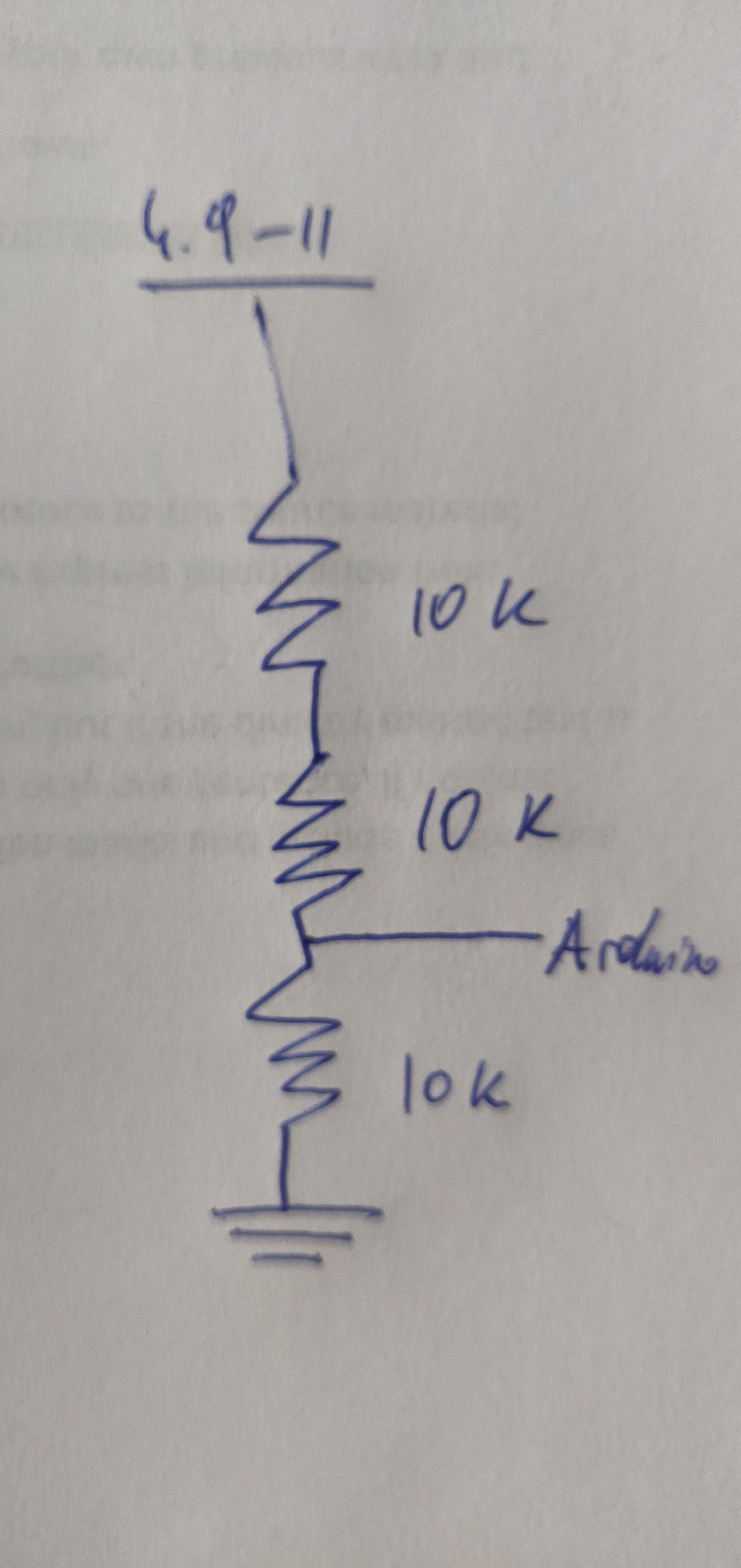
The highest I'll get to is 11 V.
My current setup is in the image I attached.
That would put me at 3.67 V. Which isn't great. But I only have these resistors: 10, 100, 220, 330, 1 K, 2 K, 5K, 10 K, 100 K, 1 M.
I'll add the resistor before the analog pin to be sure, though.
EDIT: What if I put 5 K and 10 K in series, then divide to the analog pin and then a 10 K again? That would leave me with a maximum of 4.4 V, right?
Ok, my project just became a little more complicated, so I'll have to tell you the entire story behind this project for context:
So my doorbell can make two chimes, one for the building's entrance door and one for the apartment door. Which sound happens depends on the voltage drop that happens when you push either bell button.
At 10.7 it doesn't ring, at 8 it rings the house doorbell and at 6 it rings the house doorbell.
Now there is another wrinkle to this that's annoying: the entire intercom system is AC. In other words I had to use a DC rectifier and then get the voltage down to prevent blowing up my Wemos board, which - when the voltage changes - sends me one of two telegram messages via home assistant.
BUT there is a problem: my calculations were apparently off, because instead of having 4.4 V I get exactly 2 V when the bell isn't ringing, and when someone rings the building's doorbell the voltage actually goes UP to 4.3 and increases even further to 4.75 when the apartment doorbell is rung.
First of all, what have I done? Why? And also, that's not all:
The weirdest thing is that I can read this voltage when I put the multimeter clamps on the anode and between the last two resistors of the voltage divider; however, measuring voltage between the point between the last two resistors with ground (both from the arduino and a cable) the voltage is freaking ZERO?
What gives? Can anyone explain what's happening? Did I not get the ground right?
Hi,
After you have rectified the AC, have you got a smoothing capacitor to get proper DC?
It sounds by those DMM readings you are looking at rectified AC, but no filtering/smoothing.
Can you please do a circuit diagram including the AC feed and the controller, you may have grounding problems because of the AC doorbell switch circuitry.
And no, there is no mix up. Voltage INCREASED after the second resistor...
In other words, what you are saying, what I have here is not in fact DC but rectified AC?
I thought rectified AC is DC...
To give some more context to the horribly drawn diagram: the five circles at the top correspond to the five pins in the intercom with their corresponding cables coming out of the wall (not drawn here here).
The voltage between pins 3 and 5 changes when the doorbell is rung.
As a side node, the circuit for the door buzzer downstairs is between pins 4 and 5.
EDIT: also, isn't a rectifier already a glorified capacitor? If I put a capacitor after that, won't that massively delay the voltage change?
LucasRohr:
EDIT: also, isn't a rectifier already a glorified capacitor? If I put a capacitor after that, won't that massively delay the voltage change?
Rectified AC is just voltage pulses, all in the same direction, not a continuous voltage.
The choice of capacitor will govern the ON / OFF apparent delay when switched.
Tom...
TomGeorge:
Rectified AC is just voltage pulses, all in the same direction, not a continuous voltage.
The choice of capacitor will govern the ON / OFF apparent delay when switched.
Tom...
ok, interesting.
So what "choice" would you recommend?
Keep in mind that people on average probably only ring a bell for about half a second to a second. Is that even viable?
Edit: also, what would happen if I measured between resistor 1 and 2 with my arduino right now, as it is?
Would I get a measurement of 2V?
Because right now, the voltage does not seem to fluctuate. At the very least the fluctuation is so fast, my multimeter can't detect it. As long as I can measure it with my arduino, I don't care what current it is. XD
dave-in-nj:
Rectified voltage goes up by 1.414 time AC.
Use the full bridge rectifier with a capacator.
Measure the new voltages for each state
Calculate the new voltage divider
Bob's your uncle
I did all of that without the capacitor, so far.
I have the different values associated with each state, why can't I just use those? What would happen?
Keep in mind that I'm not trying to power anything with it.
I'm sorry for asking so many potentially dumb questions but I'm trying to understand.
AC will not be steady so you can do some smoothing in software.
The proper way is to use a cap. Since you are using large resistors the cap does need to be large but MUST be rated for double the voltage of the highest in the system.