Hi... I am trying to measure voltage difference using ads1263 with arduino mega/Teensy 4.1. When i measure only one differential input pair of ads1263 (A0-A1), the sampling rate is very fast but as i use more than one pair of ads1263 (like A0-A1, A2-A3 etc.) i am getting only 3-4 sampling rate... In the code, if i reduce conversion time less than delay(55) it gives only 0 voltage for all channel ... i have tried with drdy pins as well but having same issue ... anyone please help ... Thanking you in advance... Here is the code .. I want more than 500 sps per channel ...
Don't use SPISettings alone
Use instead SPI.beginTransaction(SPISettings(1000000, MSBFIRST, SPI_MODE1)); Only do once in setup()
Only use SPI.endTransaction(); when you are done with the SPI bus and you want to use the pins for something else, otherwise don't use it.
OK, I did not think it would make a difference but it best to do it the right way.
If you have FIR filter selected, the fastest sampling rate is only 20SPS
The filter type is set in register 0x04 but you are using reg 0x01.
What sampling rate do you need?
There are a few libraries available that might make using it easier
Your topic does not indicate a problem with the Arduino Command Line Tools and therefore has been moved to a more suitable location on the forum.
Hi, @das_gopal_1998
Welcome to the forum.
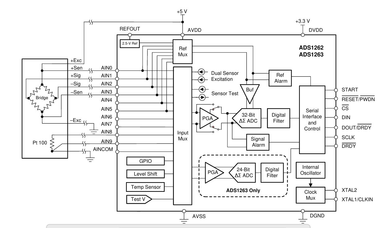
Are you aware that the ads1263 is only one ADC that is multiplexed to each of the 10 inputs.
If you are only using A0 and A1, you only have the two conversion times.
If you add A2 and A3, that is 4 conversion times.
The conversion time does not change, the acquisition time does.
The more inputs you want to read, the longer it takes to read them all.
Tom.... ![]()
![]()
![]()
![]()
at least 500sps per channel... is it possible
Yes ... but it should multiplex with at least higher sps??
There will be a tradeoff between gain, noise and speed.
You will need to use the DRDY line.
Try setting the sampling rate to 7200SPS and the filter to sinc4
Set ADC Conversion Run Mode to pulse
The filter is selected in register MODE1 (address 0x04)
select sinc4
Why have you gone back to using SPIsettings and beginTransaction when you did it the right way in post #3 ??
Modify the code you show in post #3
But still not more than 3-4 sps
No it's still wrong.
I suggest you spend some time reading the datasheet and learn how to set all of the registers and what they mean.
The write command is 0x40 NOT 0x42.
The device will return 6 bytes when you do a read
I need to know what you are trying to measure, the frequency and min and nax voltage values.
I also need to see a schematic of your ADC circuit.
I also need you to do what I ask and not something completely different as you have been doing. I can't help if you just ignore what I ask you to do.
See post #17
I can't help if you continue to ignore my suggestions and questions.