Hey,
I'm a little new to arduino. But I have been using them for a while and now familiar with them. I'm building a line following robot for a contest. But I want it to be more advanced.
As we know usually line followers are programmed to switch off one wheel when the relevant sensor is out of the line. I want some more precise control for it.
I saw some videos of robots using the PID method. It's good.
My robot has two "powered" wheels in the middle and two caster balls in front and back. Awkward design but you will see why I have to do so in the questions.
These are what I am using.
#Geared motor with wheels- eBay
#IR sensor TCRT5000L TCRT5000- eBay
#L298N Motor driver- eBay
(I am going to build a motor shield too.)
Now these are what I want to know.
1)Because of the terms of the contest I can't use ready-made modules. (Eg-QTR-8RC, L298N module). I had to make a P.C.B even for the motor driver, and the arduino itself! anyway they function just as the original ones.
The track which the robot has to follow is black and contains a "Y" junction(doesn't matter which way the robot takes) , a sharp 90 degree turn and curves. And has a width of 3cm. The starting point is a 25x25cm black square and at the end of the line there is a 25cm diameter black circle where the robot should stop automatically. (Image 01)
How many sensors should I use as you think? And please give me some idea about the arrangement of the sensors too.
2)I thought of performing a special manoeuvre at the sharp 90 degree turn. It is something like this. The robot goes straight and stops at a certain point on the 90degree turn. And the two wheels rotate in the two opposite directions making the whole robot "rotates" until it faces and align with the other side of the turn(Y side). It's hard to explain. I have uploaded pictures too .Hope you get the idea. This is why I'm going to use two caster balls back and front.
I drafted one using 8 sensors. At the 90degree turn it works like this.
1- moving forward. Sensors read 00111100(image 2)
2- the sensors just get the side of the turn.(image 3) The sensors read 11111100
And command like
"Move forward for a 'x' time.
Then stop. Rotate the wheels in two opposite directions for a 'y' time or until the sensors read 00111100."
I adjust x and y until I get the robot turned perfectly aligned with the track.(image 4)
Is this possible? Please point me out to some code guides on the web.
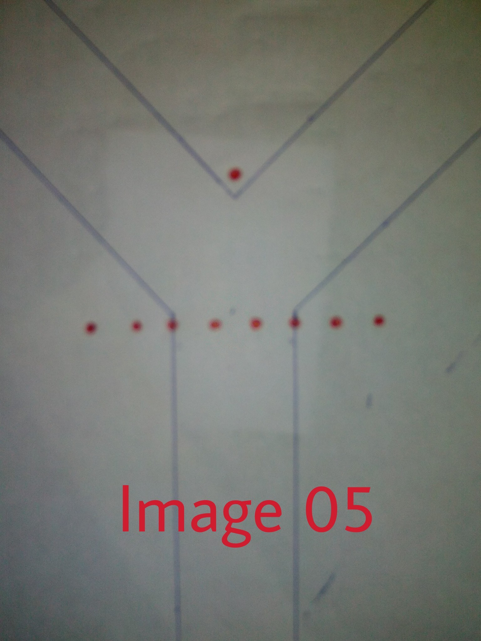
3)I have no idea about what to do at the Y junction. I think I should use another sensor in the middle a head of the others. Will it work?
Any comments?(image 5)
I studied PID a lot. What I can't figure out is how to get the sharp 90 degree turn and the Y junction decision.
#This is a time based contest and the robot has to be fast.
Any tips,tricks,guides or anything are welcome. Thank you very much.
After completing I will post a clear description of everything.