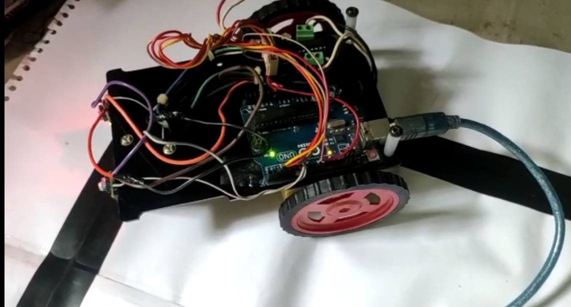
Hello all, I'm doing project on line follower using Arduino UNO with 2 sensors and L293D with 2 motors. The sensors are working properly but robot is not following the curve path, it just follows straight line and then start to rotate itself. Please help me in this. The programming of robot is as below;
/*------ Arduino Line Follower Code----- */
/*-------defining Inputs------*/
#define LS 7      // left sensor
#define RS 6      // right sensor

/*-------defining Outputs------*/
#define LM1 5       // left motor
#define LM2 4       // left motor
#define RM1 3       // right motor
#define RM2 2       // right motor

void setup()
{
 pinMode(LS, INPUT);
 pinMode(RS, INPUT);
 pinMode(LM1, OUTPUT);
 pinMode(LM2, OUTPUT);
 pinMode(RM1, OUTPUT);
 pinMode(RM2, OUTPUT);
}
void loop()
{
 if(digitalRead(LS) && digitalRead(RS))     // Move Forward
 {
digitalWrite(LM1, HIGH);
digitalWrite(LM2, LOW);
digitalWrite(RM1, HIGH);
digitalWrite(RM2, LOW);
}
 if(!(digitalRead(LS)) && digitalRead(RS))     // Turn right
 {
digitalWrite(LM1, LOW);
digitalWrite(LM2, LOW);
digitalWrite(RM1, HIGH);
digitalWrite(RM2, LOW);
 }
 if(digitalRead(LS) && !(digitalRead(RS)))     // turn left
 {
digitalWrite(LM1, HIGH);
digitalWrite(LM2, LOW);
digitalWrite(RM1, LOW);
digitalWrite(RM2, LOW);
 }
if(!(digitalRead(LS)) && !(digitalRead(RS)))     // stop
 {
digitalWrite(LM1, LOW);
digitalWrite(LM2, LOW);
digitalWrite(RM1, LOW);
digitalWrite(RM2, LOW);
 }
}
You have poor naming LM and RM. Call them for what they are. There are 2 left motors but they are obviously doing different things because you code them separately. Since we can’t see them or how they are wired it is hard to make suggestions
Your topic has been moved to a more suitable location on the forum. Installation and Troubleshooting is not for problems with (nor for advice on) your project.
okay got your point thanks for the suggestion and i'm attaching the circuit diagram of my project in this just Left and right sensors are connected on 6 and 7 port of arduino and motor side connection is done on 5,4,3 and 2.
Ya i know, i need to use 12V. Actually first i used my adopter which is 12V but my project is not working with that so I tried 9V and then i tried my power bank(20000mAh). Project is still working properly with power bank on straight line.
you should probably work out what voltage and current your components require/will tolerate and size the battery accordingly rather than trying multiple types at random
Your code has no reference to motor A or B, if you stick to common terminology it will not confuse.
Have you tried putting in a serial print here and there to see what the output is?
4 * 1.5 V AA batteries are quite good. They provide more current than the 9 V battery.
Remove the wheels or lift up the wheels and move your car by hand over the line to see how it reacts to the line.
If it doesn't react at all, no wonder it drives a straight line.
If it reacts, but it still drives a straight line, when you put the wheels down, the speed is too high. It drives off the line and only slightly notches when crossing the line. My guess is that since you have two sensors, the line is supposed to run between the sensors. To allow higher speed, you could have a wider line and the sensors farther from each other.
If your sensors can measure analog, that could make the car go smoother. Instead of stopping one motor to make the car turn, just make it go slower according to how much the analog signal is dropping.
As you all suggested, I tried with serial print and modified my code but now it's turning left and right properly but not following the line straight or moving forward
Thank you for your valuable time and suggestions. I already tried it sensors are react properly but when i put sensors farther from each other they sense the line but don't follow it and my sensors can't measure analog signals.
But the thing is your car will never run a straight line. One wheel is rotating slightly faster than the other due to varying voltages in the wires. You have three modes there: Both motors run, only left one runs, only right one runs. Don't expect the car to be perfectly lined up with the line at any moment. The moment the line gets under one sensor, the car turns a bit. The moment the line is not under the sensor anymore, both motors run again. At that point the car is not lined up with the line. It is probably doing some zig zag along the line.
What your car does is it makes one motor stop completely as soon as one sensor is over the line. It could instead slow it down just a little. That way the new direction would not be too much off the actual line direction. But the turns the car makes are not so sharp, which means it might easily drive off the path. That would require wider line and less sharp curves of the line.
Instead of using an analog sensor, you might use the digital sensor for summing. Have your program record say 10 last readings and take the sum of them. If sum is 0, put full speed on motor. If sum is 10, stop the motor. Any other sum inbetween adjusts the motor speed accordingly. That would kind of mimic the analog approach.
That could even work with just one sensor, trying to follow the edge of the line, like in this video:
I've used one analog sensor here. I measured the analog value when sensor was above the black tape. I measured the analog value when the sensor was above the grey floor. I aimed for the average. Whenever the measure was off the average, I slowed down either motor. I had to make the line wider at some points of the track.
(The other car chasing the line follower is radio controlled.)
As you suggested me, I change my sensors with analog one and now its working perfectly. Thank you so much for that. But now here is little issue in turning. As shown in picture on this point it tries to go forward but can't so please help me in this.