@anon57585045 Still working on component placement before drawing out any traces but ive made the bottom part one giant ground plane.
Next question - widely overlooked - hand parts placement/soldering, or machine? For hand placement, you are wise to adopt some extra precautions.
Yeah, because most analog input applications aren't that critical.
pretty much all the components are smd except for the actual buttons/switches which are through hole components so ill probably have to hand solder those.
SMD can still be hand or machine soldered. So which one? Through hole parts are machine soldered using "wave soldering". So a hybrid board has two soldering stages if it's entirely machine soldered. But the wave soldering can't be done on the SMD component side. In fact for hybrid boards, there can be no SMD parts on the TH solder side.
Ill have to check on the jlcpcb website for more details but I was hoping to have everything machine soldered using their service and I think they can only do 1 side for the smd soldering of components not double sided.
Worst case ill just order with the smd components soldered and do the through hole myself.
I don't use that fab, but I think they would do 2 sides for additional cost. However, usually there is no need to go double sided. Single sided is a simple process - screener, pick and place machine, then direct to oven.
Why all the diagonal placements? You've got lots of space on the board.
I want to keep things compact and in one main area so that o have enough space to shift the buttons around and I’ll probably contour/cut the corners in some way as well
stupid question is H1 ISCP a pin header
Yea it’s a 6 pin header for pins reset, ground, 5v, sck, mosi, and miso.
This topic was automatically closed 180 days after the last reply. New replies are no longer allowed.
Opened at the request of the OP.
Hi,
I would like to thank everyone in this thread who helped me and gave me advice. I did end up successfully completing the electronics portion of this project. I abandoned it a long time ago because i sort of got annoyed/frustrated with the 3d printing/creating as plastic housing part for the device.
That being said I want to share my project files here in case anyone is wanting to do something similar for themselves. the board/schematics have buttons on them, but if you remove all the buttons then you have a working barebones atmega32u4 that you can add to/modify to whatever you want. I used easyeda from jlcpcb to do all of the schematics and pcb work so ill post that file here as well as a pdf of the schematic itself if you only want/require that.
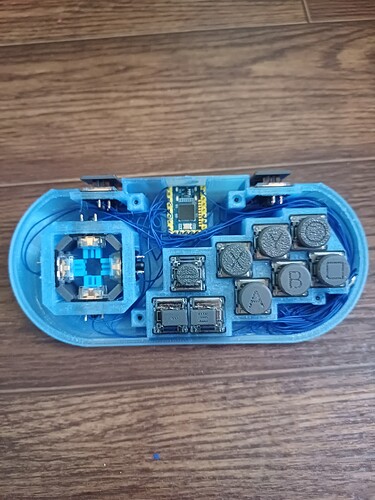
Ill also post some pictures of the device as i did have it made and ordered to my residence and it works and everything.
Feel free to ask me any questions although I may not know or remember specific details as it has been a very long time since I've looked at or touched anything on this project
Thanks again.
PCB_PCB_Atmega32u4-Barebones_2024-05-09.json (432.3 KB)
Schematic_Atmega32u4-Barebones_2024-05-09.pdf (94.0 KB)


