However I also want the design to be electrically safe if you know what I mean. I found another persons similar design which had one difference in the way the usb was setup . they have esd protection and I wondered if this is even something that is necessary or required.
On the same point, are there ways to make the current bare minimum schematic more safe electrically similar to what has been done in that usb example? Is it even necessary to do and should I even consider doing it?
Ill only be adding digital push button switches using the internal pull up as i want to create my own xinput gamepad.
@CrossRoads I figured I might as well ask if you have any input on this since I think you may have created the original base schematic that I am referring to from the other topic.
No, I don't know what you mean.
Safe for humans to touch?
Safe for your laptop to connect to?
Safe from the EMP generated by an H-bomb?
Safe from hackers?
Safe from the electrical noise associated with <components you haven't told us about>?
Safe for a medical device connected to a human body, powered from a 240V wall socket?
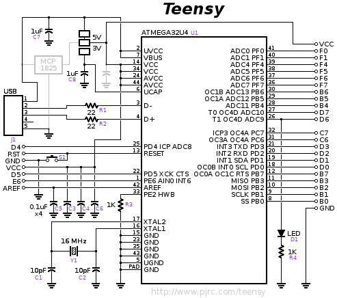
The schematic shown in OP is for USB-C, which probably requires very specialized protection to allow for "superSpeed" data. Some Arduinos have different protection (PGB1010604 Varistor on Uno, maybe.) A 32u4 probably doesn't need the same thing, since it's only "full speed." And Many Arduino-like boards seem to survive just fine without any ESD protection on the USB data lines (for instance PJRC Teensy2, Adafruit Feather 32u4, Sparkfun 32u4 breakout... All good examples of pretty minimal 32u4 systems with good track records.)
Here's the PJRC Teensy 2 schematic, for example:
Oh wow ok I did not know he was not with us anymore. I'm new to Arduino and only signed up for the forums just yesterday but on my search found many old forum posts where he had posted.
@westfw I guess by safe I meant safe from catching on fire or something like that.
I meant safe by whatever electrical standards most of our daily consumer devices go by.
So that is to say FCC or CE standards? You know any of those logos you might find on your electronic device. I assume they require a device to be safe from fire or have certain tolerances, whatever the case may be. Sorry I was not clear enough about that.
I also have another question about the base circuitry unrelated to safety. What exactly would I be losing out on if I don’t include the hwb circuitry or the reset circuitry. That is to say I would only have the isp pins circuitry for programming the chip. I realize the isp pins include a connection to the reset pin. Does not having the rest of the reset circuitry present make it so that the isp circuitry won’t work as expected anymore?
Probably the fuse is the most important thing WRT "don't catch fire", especially as standards and non-standards want to push more and more power over the USB wires. Most Arduino boards have a 0.5A fuse, since that's the "USB 2.x power delivery max", and provides the max "legal" power for shields and other stuff connected to the board. But if you're designing a specific thing that has a lower limit on how much current you expect it to draw, you might want to think about a smaller fuse (and/or pay attention to "trip current", vs "rated current.")
FCC is about radio spectrum emissions and not interfering with other nearby things. That has some safety implications in medical environments or aircraft, but isn't specifically a "safety" thing.
UL approval (and I think CE as well) are the main safety-oriented standards, but they're mainly concerned with keeping the high-voltage from your wall socket from zapping people using your product. They're not very applicable to low-voltage gadgets powered over a USB connection, and they tend to be "whole box" oriented and inapplicable to "board-like" devices. (eg they include stuff like "ventilation holes for cooling will be small enough that a standardized "human-finger probe" can not poke through and touch a high voltage wire.) Many low-voltage devices push off such safety issues to an external power supply, and the best thing hobbyists can do is probably NOT use one of those extra-cheap power-supplies with possibly forged credentials.
Are the icsp pins alone sufficient to program the chip even if it has no bootloader and is blank( or am i losing out on something by not having the hwb and reset circuits) Are there any potential negative consequences of not having either of those two circuits? OR do I need at least one of them?
Well from what I understand having searched online and finding different information and also in combination with what I found in the datasheet;
Apparently if the hwb pin is set to high on boot then it skips the bootloader and just runs whatever program is already set (if there is one at all). If however that pin is set to ground on boot up then it will always run the bootloader. Im not sure what happens if the pin is floating though.
Also apparently once either of those two situations has occurred; the pin can supposedly then afterwards be used as a general purpose i/o pin.
I'll have to do more investigation about the reset pin/button in the datasheet but from what Ive read online when you press it all it does is restart the program that is already set on the chip. So its not the equivalent of powering off and on but its just a button that will when pressed restart the existing program on the chip (and supposedly pushing this button should never result in the bootloader executing first but im not 100 percent sure about that?)
As for the isp; well I know that its used to flash programming onto the chip using an avr programmer(the 6 pin device, and I know theres a way to make an arduino function as a programmer as well), and that programming it in this way may or may not also overwrite the bootloader depending on what you are flashing onto it I think.
This is what I found about it in the datasheet:
"The On-chip ISP
Flash allows the program memory to be reprogrammed in-system through an SPI serial interface, by a
conventional nonvolatile memory programmer, or by an On-chip Boot program running on the AVR core. The
boot program can use any interface to download the application program in the application Flash memory.
Software in the Boot Flash section will continue to run while the Application Flash section is updated, providing
true Read-While-Write operation."
The thing is im also sure I read somewhere that if the chip is completely blank (as in it does not even have a bootloader) then you cant use the isp method to flash the chip at all or something like that which im really confused about. Then I also read something about setting fuses but thats way beyond my comprehension at this point in time as I think that involves customizing the chips behavior at an even more intricate level than im currently familiar with.
You can read all kinds of BS "somewhere". Do you have a link?
The chips come blank from the factory. I can tell you from experience that I've purchased boards with unprogrammed MCU's. So I burned a bootloader using the ICSP. You are way overthinking this... it's routine and well known, just do it. I believe you do need access to the RESET pin to make the upload work.
they say "The 32u4 ships from the factory with the DFU USB bootloader already programmed into the top pages of flash memory. The fuses are also programmed to run the USB bootloader when the HWB button is grounded at power up or reset. Be aware that you must have the correct frequency crystal connected to use the USB boot loader.
You can always use the ISP connector to program the 32u4 with or without the bootloader code on the chip. But if you erase or otherwise overwrite that atmel bootloader code, then that ability is gone. You then need to always use ISP to program the chip (unless you re-program a bootloader into the chip via isp).
Be sure to read up on the function of the fuses in the datasheet.
Also note, finding a .hex file of the atmel usb bootloader to restore the chip to the way it came from the factory might be difficult (it used to be)."
The only chip information you can really depend on, is the manufacturers information. And then, not always. If they don't guarantee a factory programmed bootloader, you can assume it's not there.
Also, bad code can wipe the bootloader. So you need a way to rewrite it in that instance.
@anon57585045 alright fair enough.
I guess the reason I was asking/wondering if I even needed the reset and hwb circuitry (maybe even the icsp pins) is because i know some pcb manufacturers can provide a service of programming the chip for you before they send the pcbs over. Im guessing that this case really only applies to some sort of finished product where you know you wont be changing the programming at all though in the future. Thank you for taking the time to read and answer my questions btw its been very helpful and I very much appreciate it.
I was trying to recreate the barebones schematic and Im wondering about the part with the VBUS,VCCs,AVCCs,UVCC part. Im not sure if I've interpreted it correctly.