Hi,
I'm building a car exhaust system with servo flap control by UNO R3. Friend and I been on this project for months already. Not able to make the servo motor flap working. Been searching on web, but not much info on 12V servos coding and wiring. We are beginners, so hopefully some nice ppl willing to give us some help.
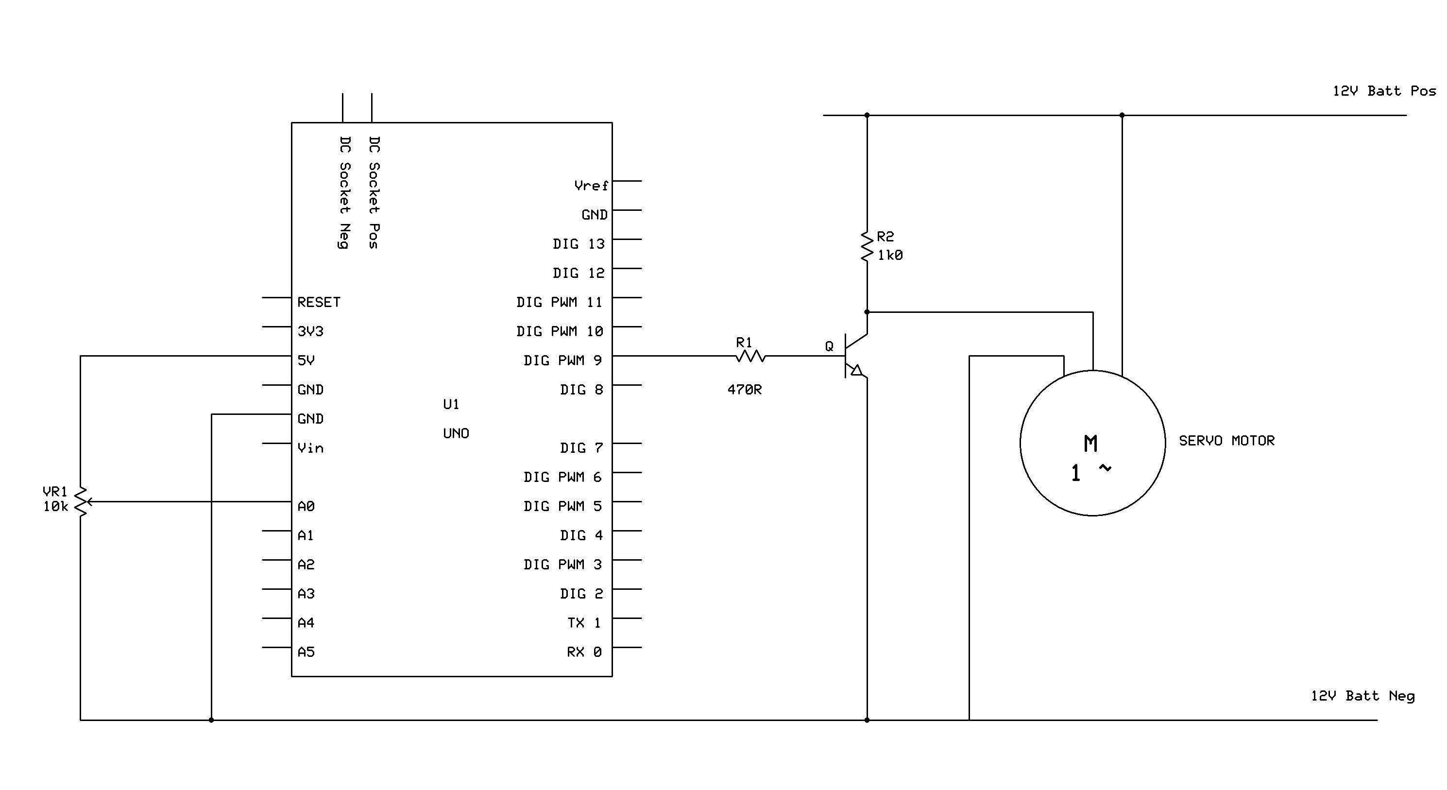
Goal: On/off switch or "sport mode" button signal through Uno R3, open/close 2 12V servo motor on exhaust system.
Servo motor: 12V, 3 pins (12V, ground and PWM signal). Operating value measured off from a factory car (same servo motor). Flap opens: 12V, 100 Hz, 92.80% duty cycle. Close: 100 Hz, 9.92%.
Coding:
unsigned long duty1,duty2;
// Duty Cycle in terms of a percentage.
unsigned long plus;
// Value read from A1, in case plus mode is activated
float xxx;
// Float numbers to calculate duty for PWM 1 and PWM 2
float yyy;
unsigned long pwm1;
// Value read from A0 and A2 to give PWM duty cycle output in terms // of 0-5V
unsigned long pwm2;
void setup(){

pinMode(9, OUTPUT);
pinMode(10, OUTPUT);
TCCR1A = _BV(COM1A1) | _BV(COM1B1) ; // phase and frequency correct mode. NON-inverted mode
// TCCR1A = _BV(COM1A1) | _BV(COM1B1) | _BV(COM1A0) | _BV(COM1B0) ;
//phase/frequency correct mode. SELECT THIS FOR INVERTED OUTPUTS.
TCCR1B = _BV(WGM13) | _BV(CS11);
// Select mode 8 and select divide by 8 on main clock.
}


void loop(){

// Program that lets different values on A3 choose different values of frequency, e.g. 100,200,400,500,1k,2k,3k,4k,10k,
//etc in relation with a free input.
if (analogRead(A3) <100) ICR1 = 10000; // 100Hz - Default value to 100Hz for A3 = 0V
if (analogRead(A3) <200 && analogRead(A3) > 100) ICR1 = 5000; // 200Hz
if (analogRead(A3) <300 && analogRead(A3) > 200) ICR1 = 2500; // 400Hz
if (analogRead(A3) <400 && analogRead(A3) > 300) ICR1 = 1000; // 1000Hz
if (analogRead(A3) <500 && analogRead(A3) > 400) ICR1 = 500; // 2000Hz
if (analogRead(A3) <600 && analogRead(A3) > 500) ICR1 = 333; // 3000Hz
if (analogRead(A3) <700 && analogRead(A3) > 600) ICR1 = 250; // 4000Hz
if (analogRead(A3) <800 && analogRead(A3) > 700) ICR1 = 100; // 10000Hz
if (analogRead(A3) > 800) ICR1 = 1000; // Default value to 1kHz for A3 = 5V

//ICR1 = 1000; // for ICR1 = 1000, frequency = 1kHz.
pwm1 = analogRead(A2); // read duty from A2 for PWM 2
pwm2 = analogRead(A0); // read duty from A0 for PWM 1
xxx = float(pwm2);
// Turn read values from the POTs to float for mathematical
// adjustment.
yyy = float(pwm1);
xxx = xxx * ICR1;
// Multiply with ICR1 and divide by 1023 to give required percentage
yyy = yyy * ICR1;
xxx = xxx / 1023;
yyy = yyy / 1023;
//Assign values to OCR Registers, which output the PWM duty cycle.
OCR1B = int(xxx);
OCR1A = int(yyy);
}
With that, I don't even get PWM out of Uno.
If anyone can help or start fresh.. please give me advice.
Thanks in advance