Hello,
I have been working on a project where my Arduino will act as power to a switch in the form of a MOSFET but I have had trouble in actually getting the circuit to work correctly. Whenever my Arduino sends a signal it seems that no change occurs. The solenoid requires 0.5 amps of current and 6-9v which I know my voltage source can provide. Below I will include my circuit design of the circuit I thought would work and would appreciate advice on what I may have done wrong or what misconceptions I have had. I am fairly new so I understand I likely have made many mistakes so I am open to any advice or suggestions possible.
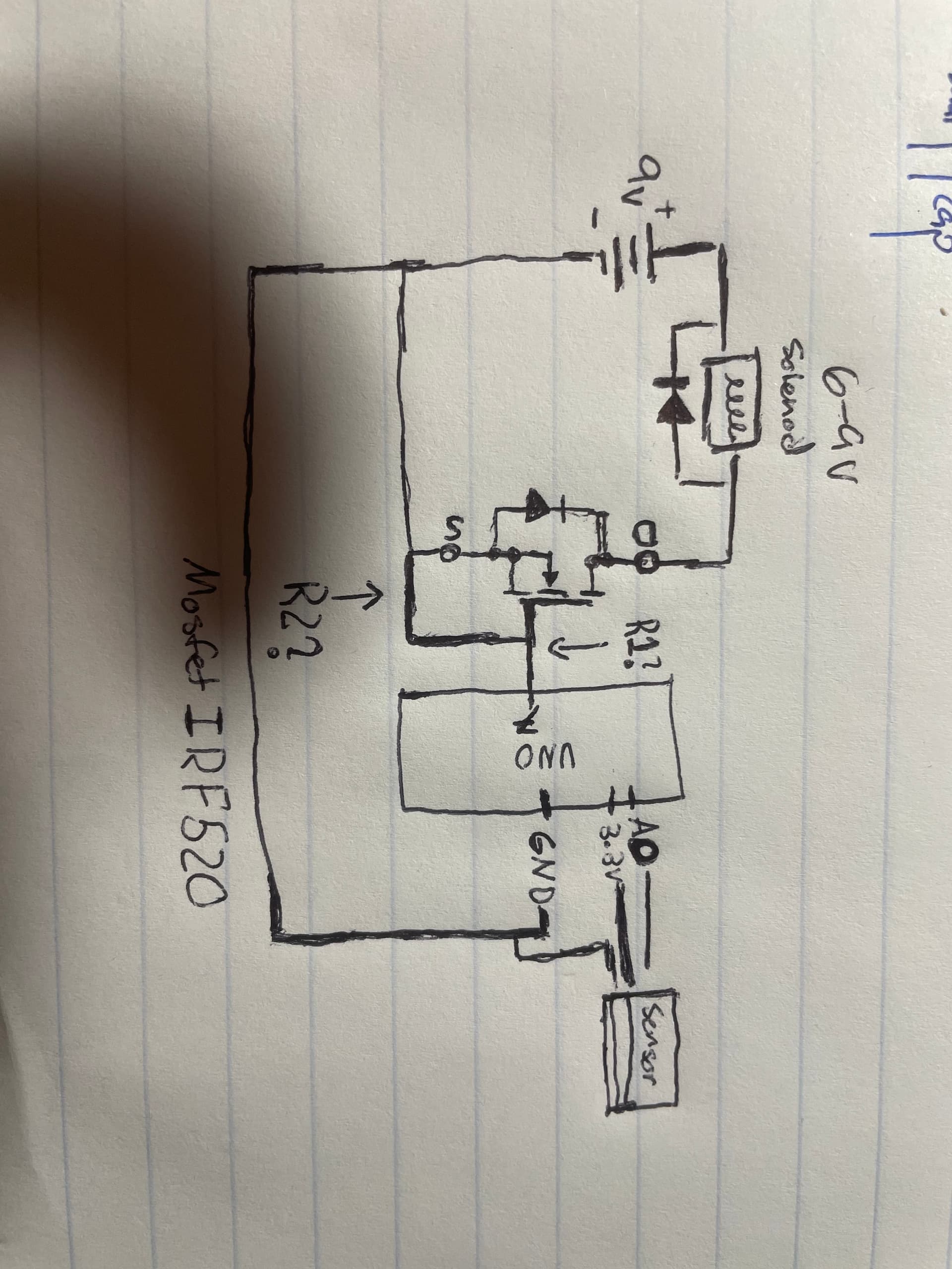

Can You present the "9 volt source" a bit closer?
Thank you for the advice. I will look into getting a logic level mosfet and will add the R1 and R2 as shown. When you mentioned the 'short' your were referring to where the R2 resistor goes correct.
If I might ask, what do you mean when you say present if I might ask. Do you mean drawing it closer?
Yes ( the line I covered in white )
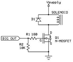
Here is a circuit that should work for you. It will keep thesolonoid off until your code enables it. If you use an appropriately avalanche rated MOSFET the diode D1 is not needed.
Which Arduino (there are more than 20 different Arduinos).
What 9V source are you using ( hopefully NOT a PP3 block battery)?
Tell its data.
Thank you very much for this circuit design. I appreciate it immensely. Also, when you mentioned the avalanche rating, how would one calculate that?
It is an Arduino Uno and the power source right now is a PP3 block battery just to test but I will, hopefully, move to a rechargeable 9V that's Solar charged.
Right now it is a simple 9v alkaline battery with 1.7 ohm resistance at 1 kHz.
Use the circuit gilschultz was kind enough to post in Post #7. Yes, you want a logic level MOSFET and low side switching. There are plenty of logic level N channel MOSFETS available. I would run a FQP30N06L but there are plenty of others which will also work.
Ron
A 9
PP3 battery is 9 volt source but not a power source. You need a power supply that can supply current, not only 9 volt.
It is not a calculation but a measurement made by the MOSFET manufacturer. It is explained in there data sheet. We started that at Siliconix many years ago. It is controlled by the manufacturing process. They will test many devices from several lots to get a value then each lot is tested to be sure the process is exceeding the requirements. It is considered a destructive test.