Alright, so I am designing my own air ride system using the arduino and 8 solenoid valves, 4 rotary position sensors, and a touchscreen for a controller. I have done a fair bit of research and have my touchscreen working with the menus that I want already done. I have not ordered any parts yet, just trying to get the wiring schematic all ready to go before I start ordering parts.
These are the valves I will be going with (link below). they are 12V, 3/8", normally closed solenoid valves (part no: VXD2130-03N-6G1B) http://www.smcpneumatics.com/pdfs/VXD2.pdf
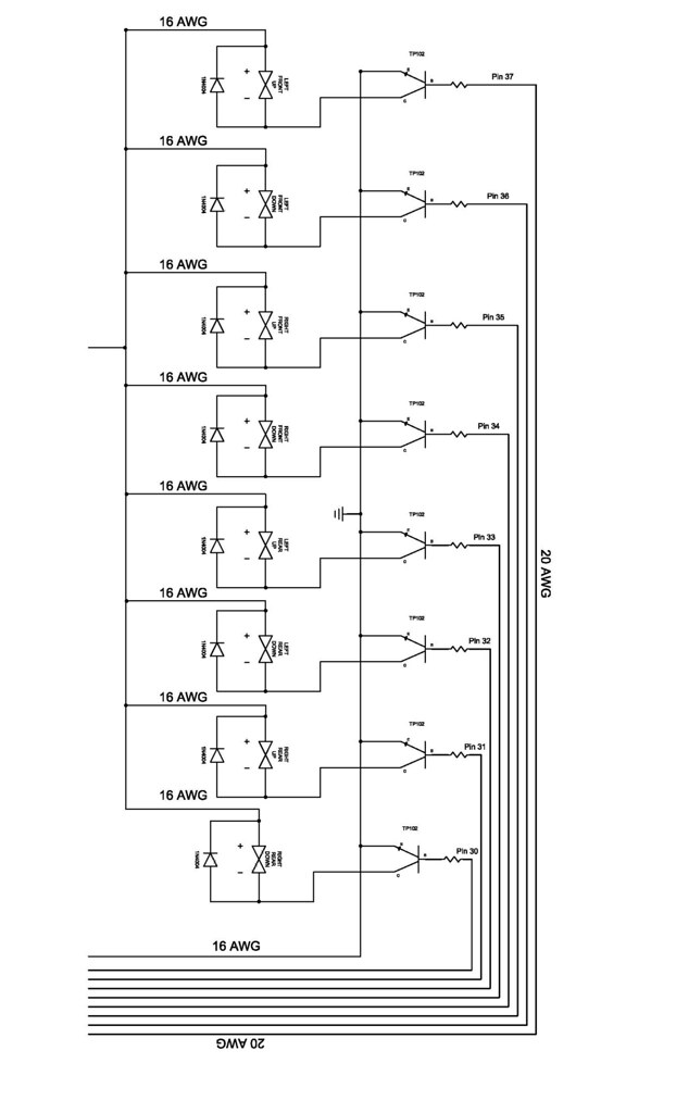
I have an arduino mega board. I based my wiring schematic around the playground solenoid tutorial (Arduino Playground - HomePage). I basically used this same schematic 8 times.
From top to bottom they will be connected to pins 30-37. My schematic:
rogerClark:
Your wiring diagram is useless unless you label the nets, I.e the connections in each of the 2 parts you have posted.
It's impossible to tell which pins on the Arduino connect to which transistor etc.
Btw, what diagramming tool are you using.?
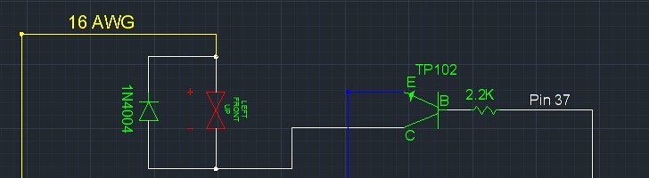
I'm using AutoCAD for my schematic. Sorry, I guess I wasn't detailed enough. I've added pin numbers to the wires and also part numbers/sizes for the resistors (2.2K), diodes (1N4004) and transistors (TP102). I also labeled the pins on the arduino mega board that I was asking about. in my previous post.
You need to label EVERY net in order for us to know whether it's correct or not. For example, the 16 AWG wire connected to all the tops of the transistors (sorry, I can't tell if that's the collector or the emitter... the symbols are too small) is connected to what exactly? And the little branch connected to one end of each solenoid is connected to what? The 5V and GND pins on the left side of the Mega are connected to what? We can't just guess. A schematic that doesn't have this information isn't much help to anyone. Speaking schematics... here's what a good one looks like:
According to the schematic, yes both of the pins on one side are connected to GND and both of the pins on the opposite side are connected to 5V.
Hi, I would regard this schematic as half finished, most of the text is overrunning the wiring or component borders, no sheet borders, no title block.
I'd be ashamed to post a supposed completed diagram.
Tom.......
PS Even CAD schematics take time, so spend bit more time to make it readable.
PPS, Eagle has way tooooo many options for simple diagrams.I use ExpressPCB for most projects, its free, quick download (ie small).
The size of wire is totally irrelevant on a schematic. We need to know what is connected to what and we need to be able to see the symbols with all the details on them.
I can't help but notice a total lack of any capacitors anywhere on the circuit.
This drawing/schematic whatever you want to call it is just for me, I'm not giving it to anyone, so there's really no need for a title block. I put the wire gauge on there so that I would know what wire I would be using for each of the different components. I did this in my free time and these pictures I have given are only screen shots of parts of the drawing. I know that it is not perfect and it was not meant to be. It wasn't made to any kind of standards, I just took parts that I wanted and threw a drawing together
TomGeorge: I'll keep ExpressPCB in mind as I need a tool like that on my personal computer. Why should I be ashamed of my drawing?
Grumpy_Mike: I'm using the playground diagram as shown below, should I add some capacitors to the circuit?
Xpendable: Here's a closer view of one of the solenoid connections. The rest of the solenoids are all connected the same. In the other drawings posted (from top to bottom) they are connected to Mega pins 37-30.
the 2.2k resistor is connected to the transistor base. The emitter is connected to ground. The collector is connected to the negative side of the solenoid and the 1N4004 diode. The positive side of the solenoid is connected to +12V.
The +5V pins of the Arduino board will be connected to the rotary position sensors that will tell me the height of the car at each corner.
Thanks everyone for their suggestions I will keep them in mind and will try to clean my drawing up and make it easier to read. I wasn't really planning on sharing it with anyone so I made it easy for me to read and know what's going on. Also, have added the whole drawing to show where each part was taken from.
This drawing/schematic whatever you want to call it is just for me, I'm not giving it to anyone,
No but you are showing it to us and asking for comments as to if it is correct so we can only judge what is on the screen not what is in your head.
Having said that I haven't spotted anything wrong.
I'm using the playground diagram as shown below, should I add some capacitors to the circuit?
Yes. It is one thing driving one solenoid and an altogether different thing trying to drive a lot. If it were me I would put a capacitor from the power rail to ground on each solenoid. A largeish one, say 100uF on each one, you might even have to go higher if you get any trouble. I would also be tempted to put a 0.1uF ceramic one across each coil.
I agree, I was just stating that's why it isn't perfect and I had to clarify some things.
I see what you're saying. I was worried about running multiple solenoids off of the single Mega board, and adding a capacitor would help me out. So I should put it in series with each diode then? From some other sites I've read that they wired a capacitor to the collector side of the transisor and the negative side of the solenoid/anode side of the diode. Or does that even really matter?
Yes. It is one thing driving one solenoid and an altogether different thing trying to drive a lot. If it were me I would put a capacitor from the power rail to ground on each solenoid. A largeish one, say 100uF on each one, you might even have to go higher if you get any trouble. I would also be tempted to put a 0.1uF ceramic one across each coil.
I, humbly, ask: Are them -the big ones- to decouple?.
A related issue: Isn't a grounding scheme -in this particular application, I mean- an important one? (I mean: fifty3bags points directly at the pins in the arduino card to ask if this is ground; it is, but i don't think that this is the place to ground the transistors emmiters )
Regards
If I needed to ground the sensors I was going to use those ground points for that. I will be using a much better ground on the car for the solenoids and compressor(s).
vffgaston:
I, humbly, ask: Are them -the big ones- to decouple?
Yes they will reduce disturbances in the power rail, caused by switching large currents, from propagating to the Arduino.
Isn't a grounding scheme -in this particular application, I mean- an important one?
Yes electrically the grounds are simply connected together but physically all the grounds from the emitters should meet at one point. That point should also be connected to the solenoid's power ground and that point should be connected to the Arduino's ground. This is known as "Star wiring" because all the wires cone from the same point like a star radiates from a single point.
It would also be a good idea to wire the +ve to the solenoid's in the same way.