ADXL345 returns 0,0,0 or -1,-1,-1

Hello,

I am trying to implement the basic sample code on my adxl345, but I keep getting 0,0,0 or random numbers from time to time.
https://www.sparkfun.com/tutorials/240

Tripeled checked the wiring(listed in the tutorial), and they seem ok.

I even tried to use a Logic Converter, until I realized I am using SPI protocol and not I2c.
Eventually, I decided to continue with the SPI protocol.
Any help would be appreciated.

Thank you in advance

If there is no aceleration in any axis (horizontal on a table) then only the Z-axis would have aceleration (due to gravity).

there is no accelartion a all.. even gravity

What happens when you move it ? (or tap it with your finger ) ?
Still nothing ?

Maybe you should show your wiring and code.

well, the code and the wiring are as specified in the tutorial page:
Arduino Pin ADXL345 Pin
10 CS
11 SDA
12 SDO
13 SCL
3V3 VCC
Gnd
GND
wiring:

code:
http://sparkfun.com/tutorial/ADXL/ADXL345_Basic.pde
my logic level converter previous wiring:

nothing seems to happen when I move the sensor, yet once in a while I get a reading- sometimes normal such as:
214,0,0
192,0,0
or completly illogical such as:
-1,-1,-1
-1,-1,-1793
-1,255,0

edit:
just found out that when tapping the chip, the values are turning from 0,0,0 into -1,-1,-1.

Post a schematic of your wiring connection.
Are you using pullup resistors on A4 & A5 ?

Post your code and list all the steps you have taken toward getting it working and if where you got your code.

I am not using those analog inputs.. I thought that's for I2C connection.
The frustrating thing is the simplicity of this tutorial.
My wiring is as follows:
Arduino ADXL345
10 -> CS
11 -> SDA
12 -> SDO
13 -> SCL
3V3 -> VCC
Gnd -> GND

Edit:
I have added two pictures - the first to show that 10-13 pins are connected properly, and the second for the GND and the 3.3v.

Adafruit's tutorial on the ADXL345 seems more detailed, perhaps it will help: Overview | ADXL345 Digital Accelerometer | Adafruit Learning System

I appreciate the gesture, but the connection is I2C, when I'd like to connect it in SPI.
Though, it did helped me to understand why the alternating between 0,0,0 and -1,-1,-1, and that's because I didn't solder the board.

Your signal names are wrong. Look at datasheet for SPI signal names.
SDA & SCL are I2C signal names, NOT SPI.

SEE PAGE 15

Arduino ADXL345
10 -> CS
11 -> SDA <==== THIS IS CALLED SDIO for SPI
12 -> SDO
13 -> SCL <= THIS IS CALLED SCLK for SPI
3V3 -> VCC
Gnd -> GND

ohh.. OK, then how should I connect it?

I'm not going to say anything more until you post your code instead of a link.

It should work with the logic level converter if you are using the wiring you linked for that .

Can you hand draw a schematic of your circuit on a piece of printer paper and take a photo of it and post it ?
Include any resistors that are in your circuit.

Well, I can do all that, but first I would like to annouce that I didn't know that I should solder the board, meaning nothing worked.
Right now, the ADXL345 is working, with a lot of noise though, and the LLC is working properly(which, at a second thought, has nothing to do with this post actually..)!
The code looks a little complexed right now, for I have merged the readings from the HR-SC04 with the ADXL.

//Add the SPI library so we can communicate with the ADXL345 sensor
#include <SPI.h>
#include <MeetAndroid.h>

#define trigPin 8
#define echoPin 7
//Assign the Chip Select signal to pin 10.
int CS=10;

//This is a list of some of the registers available on the ADXL345.
//To learn more about these and the rest of the registers on the ADXL345, read the datasheet!
char POWER_CTL = 0x2D; //Power Control Register
char DATA_FORMAT = 0x31;
char DATAX0 = 0x32; //X-Axis Data 0
char DATAX1 = 0x33; //X-Axis Data 1
char DATAY0 = 0x34; //Y-Axis Data 0
char DATAY1 = 0x35; //Y-Axis Data 1
char DATAZ0 = 0x36; //Z-Axis Data 0
char DATAZ1 = 0x37; //Z-Axis Data 1

//This buffer will hold values read from the ADXL345 registers.
unsigned char values[10];
//These variables will be used to hold the x,y and z axis accelerometer values.
int x,y,z;

/*
Sends sensor data to Android
(needs SensorGraph and Amarino app installed and running on Android)
*/
MeetAndroid meetAndroid;
long duration;
float cmPerMS,distance;

void setup(){
//------------------- Distance Sensor Begins --------------
Serial.begin (9600);
pinMode(trigPin, OUTPUT);
pinMode(echoPin, INPUT);
cmPerMS = 1/0.034029;
//-------------------- Distance Sensor Ends -----------------
//-------------------- Angle Sensor Begins -------------------
//Initiate an SPI communication instance.
SPI.begin();
//Configure the SPI connection for the ADXL345.
SPI.setDataMode(SPI_MODE3);
//Create a serial connection to display the data on the terminal.
// Serial.begin(9600);

//Set up the Chip Select pin to be an output from the Arduino.
pinMode(CS, OUTPUT);
//Before communication starts, the Chip Select pin needs to be set high.
digitalWrite(CS, HIGH);

//Put the ADXL345 into +/- 4G range by writing the value 0x01 to the DATA_FORMAT register.
writeRegister(DATA_FORMAT, 0x01);
//Put the ADXL345 into Measurement Mode by writing 0x08 to the POWER_CTL register.
writeRegister(POWER_CTL, 0x08); //Measurement mode
//-------------------- Angle Sensor Ends ---------------------
}

void loop(){
//------------------- Distance Sensor Begins --------------
meetAndroid.receive();

digitalWrite(trigPin, LOW); // Added this line
delayMicroseconds(2); // Added this line
digitalWrite(trigPin, HIGH);
// delayMicroseconds(1000); - Removed this line
delayMicroseconds(10); // Added this line
digitalWrite(trigPin, LOW);
duration = pulseIn(echoPin, HIGH);
distance = (duration/2) /cmPerMS;

meetAndroid.send(distance);
//-------------------- Distance Sensor Ends -----------------
//-------------------- Angle Sensor Begins -------------------

//Reading 6 bytes of data starting at register DATAX0 will retrieve the x,y and z acceleration values from the ADXL345.
//The results of the read operation will get stored to the values[] buffer.
readRegister(DATAX0, 6, values);

//The ADXL345 gives 10-bit acceleration values, but they are stored as bytes (8-bits). To get the full value, two bytes must be combined for each axis.
//The X value is stored in values[0] and values[1].
x = ((int)values[1]<<8)|(int)values[0];
//The Y value is stored in values[2] and values[3].
y = ((int)values[3]<<8)|(int)values[2];
//The Z value is stored in values[4] and values[5].
z = ((int)values[5]<<8)|(int)values[4];

//Print the results to the terminal.
Serial.print(x, DEC);
Serial.print(',');
Serial.print(y, DEC);
Serial.print(',');
Serial.println(z, DEC);
delay(200);
//-------------------- Angle Sensor Ends ---------------------
}

//This function will write a value to a register on the ADXL345.
//Parameters:
// char registerAddress - The register to write a value to
// char value - The value to be written to the specified register.
void writeRegister(char registerAddress, char value){
//Set Chip Select pin low to signal the beginning of an SPI packet.
digitalWrite(CS, LOW);
//Transfer the register address over SPI.
SPI.transfer(registerAddress);
//Transfer the desired register value over SPI.
SPI.transfer(value);
//Set the Chip Select pin high to signal the end of an SPI packet.
digitalWrite(CS, HIGH);
}

//This function will read a certain number of registers starting from a specified address and store their values in a buffer.
//Parameters:
// char registerAddress - The register addresse to start the read sequence from.
// int numBytes - The number of registers that should be read.
// char * values - A pointer to a buffer where the results of the operation should be stored.
void readRegister(char registerAddress, int numBytes, unsigned char * values){
//Since we're performing a read operation, the most significant bit of the register address should be set.
char address = 0x80 | registerAddress;
//If we're doing a multi-byte read, bit 6 needs to be set as well.
if(numBytes > 1)address = address | 0x40;

//Set the Chip select pin low to start an SPI packet.
digitalWrite(CS, LOW);
//Transfer the starting register address that needs to be read.
SPI.transfer(address);
//Continue to read registers until we've read the number specified, storing the results to the input buffer.
for(int i=0; i<numBytes; i++){
values = SPI.transfer(0x00);

  • }*
  • //Set the Chips Select pin high to end the SPI packet.*
  • digitalWrite(CS, HIGH);*
    }
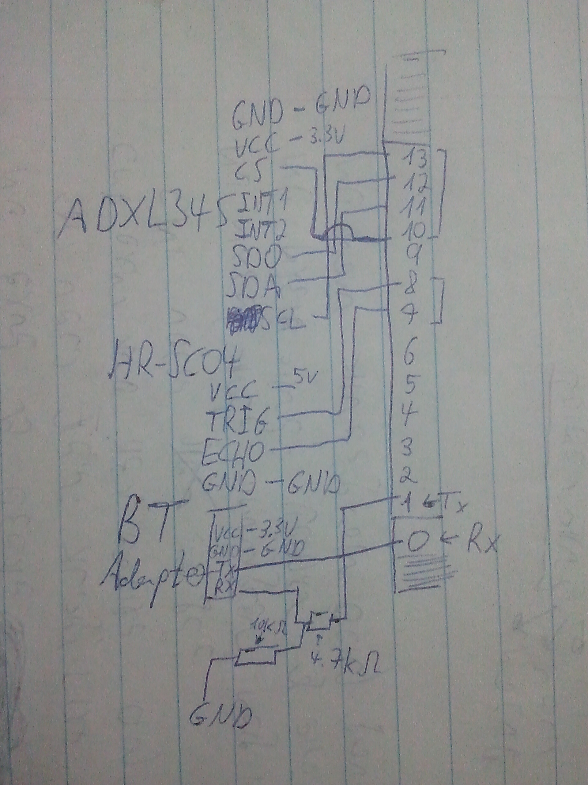
    The wiring is really too basic to draw a circuit for, but I don't mind to post it if that's neccesary.. As I have read in the tutorial, those 10-13 digital pins are also used for the SPI connection, so I believe the wiring is ok. I would appreciate any help with all the false readings, which can sometimes remain constant for a second or two(not for all the axis's at once), and with the Z axis, which does not seem to have any logical outputs at all..
    example output:
    Distance - angles
    29.98-86,-1,-16
    29.98-83,-97,-4
    29.98-18942,-129,-16
    29.98-18942,-225,-64
    29.98-20734,-1,-16
    30.12-20734,-1,-16
    29.98-20734,-1,-16
    29.98-83,-121,-16
    29.98-83,-97,-4
    29.98-23038,-129,-16
    30.49-86,-1,-16
    29.98-20734,-1,-16
    29.98-86,-1,-16
 //Add the SPI library so we can communicate with the ADXL345 sensor
#include <SPI.h>
#include <MeetAndroid.h>

#define trigPin 8
#define echoPin 7
//Assign the Chip Select signal to pin 10.
int CS=10;

//This is a list of some of the registers available on the ADXL345.
//To learn more about these and the rest of the registers on the ADXL345, read the datasheet!
char POWER_CTL = 0x2D;   //Power Control Register
char DATA_FORMAT = 0x31;
char DATAX0 = 0x32;   //X-Axis Data 0
char DATAX1 = 0x33;   //X-Axis Data 1
char DATAY0 = 0x34;   //Y-Axis Data 0
char DATAY1 = 0x35;   //Y-Axis Data 1
char DATAZ0 = 0x36;   //Z-Axis Data 0
char DATAZ1 = 0x37;   //Z-Axis Data 1

//This buffer will hold values read from the ADXL345 registers.
unsigned char values[10];
//These variables will be used to hold the x,y and z axis accelerometer values.
int x,y,z;
  
/*
  Sends sensor data to Android
  (needs SensorGraph and Amarino app installed and running on Android)
*/
MeetAndroid meetAndroid;
long duration;
float cmPerMS,distance;

void setup(){ 
  //------------------- Distance Sensor Begins --------------
  Serial.begin (9600);
  pinMode(trigPin, OUTPUT);
  pinMode(echoPin, INPUT);
  cmPerMS = 1/0.034029;
  //-------------------- Distance Sensor Ends -----------------
  //-------------------- Angle Sensor Begins -------------------
  //Initiate an SPI communication instance.
  SPI.begin();
  //Configure the SPI connection for the ADXL345.
  SPI.setDataMode(SPI_MODE3);
  //Create a serial connection to display the data on the terminal.
 // Serial.begin(9600);

  //Set up the Chip Select pin to be an output from the Arduino.
  pinMode(CS, OUTPUT);
  //Before communication starts, the Chip Select pin needs to be set high.
  digitalWrite(CS, HIGH);

  //Put the ADXL345 into +/- 4G range by writing the value 0x01 to the DATA_FORMAT register.
  writeRegister(DATA_FORMAT, 0x01);
  //Put the ADXL345 into Measurement Mode by writing 0x08 to the POWER_CTL register.
  writeRegister(POWER_CTL, 0x08);  //Measurement mode  
   //-------------------- Angle Sensor Ends ---------------------
}

void loop(){
    //------------------- Distance Sensor Begins --------------
  meetAndroid.receive();

  digitalWrite(trigPin, LOW);  // Added this line
  delayMicroseconds(2); // Added this line
  digitalWrite(trigPin, HIGH);
//  delayMicroseconds(1000); - Removed this line
  delayMicroseconds(10); // Added this line
  digitalWrite(trigPin, LOW);
  duration = pulseIn(echoPin, HIGH);
  distance = (duration/2) /cmPerMS;
  
  meetAndroid.send(distance);
  //-------------------- Distance Sensor Ends -----------------
  //-------------------- Angle Sensor Begins -------------------

  //Reading 6 bytes of data starting at register DATAX0 will retrieve the x,y and z acceleration values from the ADXL345.
  //The results of the read operation will get stored to the values[] buffer.
  readRegister(DATAX0, 6, values);

  //The ADXL345 gives 10-bit acceleration values, but they are stored as bytes (8-bits). To get the full value, two bytes must be combined for each axis.
  //The X value is stored in values[0] and values[1].
  x = ((int)values[1]<<smiley-cool|(int)values[0];
  //The Y value is stored in values[2] and values[3].
  y = ((int)values[3]<<smiley-cool|(int)values[2];
  //The Z value is stored in values[4] and values[5].
  z = ((int)values[5]<<smiley-cool|(int)values[4];

  //Print the results to the terminal.
  Serial.print(x, DEC);
  Serial.print(',');
  Serial.print(y, DEC);
  Serial.print(',');
  Serial.println(z, DEC);      
  delay(200); 
     //-------------------- Angle Sensor Ends ---------------------
}

//This function will write a value to a register on the ADXL345.
//Parameters:
//  char registerAddress - The register to write a value to
//  char value - The value to be written to the specified register.
void writeRegister(char registerAddress, char value){
  //Set Chip Select pin low to signal the beginning of an SPI packet.
  digitalWrite(CS, LOW);
  //Transfer the register address over SPI.
  SPI.transfer(registerAddress);
  //Transfer the desired register value over SPI.
  SPI.transfer(value);
  //Set the Chip Select pin high to signal the end of an SPI packet.
  digitalWrite(CS, HIGH);
}

//This function will read a certain number of registers starting from a specified address and store their values in a buffer.
//Parameters:
//  char registerAddress - The register addresse to start the read sequence from.
//  int numBytes - The number of registers that should be read.
//  char * values - A pointer to a buffer where the results of the operation should be stored.
void readRegister(char registerAddress, int numBytes, unsigned char * values){
  //Since we're performing a read operation, the most significant bit of the register address should be set.
  char address = 0x80 | registerAddress;
  //If we're doing a multi-byte read, bit 6 needs to be set as well.
  if(numBytes > 1)address = address | 0x40;

  //Set the Chip select pin low to start an SPI packet.
  digitalWrite(CS, LOW);
  //Transfer the starting register address that needs to be read.
  SPI.transfer(address);
  //Continue to read registers until we've read the number specified, storing the results to the input buffer.
  for(int i=0; i<numBytes; i++){
    values = SPI.transfer(0x00);
  }
  //Set the Chips Select pin high to end the SPI packet.
  digitalWrite(CS, HIGH);
}

Please use the "#" CODE TAGS button when posting code.

If you are capable of drawing a schematic by hand and posting a photo of it , you should do that for no other reason than your circuit is not working and we are not there to check your wiring. It's hard to tell from the photos so in this case a schematic would help.

Also, in your previous posts , you linked tutorials that are not using the code that is different from what you are using now and just posted. When you post for a problem and link code with the statement "Here is my code ..." and then later switch to some other code, you are keeping us out of the loop and we can't help you. If you change code, you need to update us immediately
so we can look at your current code.

You're right. I have merged my own code into their basic tutorial code yesterday, and forgot to update you.
A friend of mine soldered the ADXL345 board and the LLC from the bottom of the pins. I suspect maybe that's why the ADXL345 outputs are so unstable, not to mention the Z axis..
I have added a picture of the bottom LLC soldering, and a very unprofessional scheme of my circuit.

I'd like to see a photo of the soldering from directly above the board instead of from the side.

These are the proper signal names . If you are using SPI, SDA & SCL don't exist . Those are I2C signal names. the SPI names are MISO & SCLK. Also, the SDIO pin on the ADXL is the MOSI SPI pin on the arduino . If you are using SPI you should know the proper signal names. The reason you see those names on the data sheet is because in I2C mode they apply, but in SPI mode the other names apply (SDIO and SCLK)

Arduino ADXL345
10 -> CS // ( SS for SPI)
11 -> SDIO // (MOSI for SPI)
12 -> SDO // (MISO for SPI)
13 -> SCLK // (for SPI)
3V3 -> VCC
Gnd -> GND

Hi,

I'm also having the same issue using a ADXL345 in the form of a GY-291 board. I'm also trying to connect it to an Uno over SPI without any success. The GY-291 accepts 4-6V so I'm not using a logic converter. It runs fine on 5V, I2C is working well and I'm getting the expected data. But over SPI I only receive 0,0,0.

What would I test to start fault finding this issue?

//Add the SPI library so we can communicate with the ADXL345 sensor
#include <SPI.h>

//Assign the Chip Select signal to pin 10.
int CS=10;

//This is a list of some of the registers available on the ADXL345.
//To learn more about these and the rest of the registers on the ADXL345, read the datasheet!
char POWER_CTL = 0x2D;	//Power Control Register
char DATA_FORMAT = 0x31;
char DATAX0 = 0x32;	//X-Axis Data 0
char DATAX1 = 0x33;	//X-Axis Data 1
char DATAY0 = 0x34;	//Y-Axis Data 0
char DATAY1 = 0x35;	//Y-Axis Data 1
char DATAZ0 = 0x36;	//Z-Axis Data 0
char DATAZ1 = 0x37;	//Z-Axis Data 1

//This buffer will hold values read from the ADXL345 registers.
char values[10];
//These variables will be used to hold the x,y and z axis accelerometer values.
int x,y,z;

void setup(){ 
  //Initiate an SPI communication instance.
  SPI.begin();
  //Configure the SPI connection for the ADXL345.
  SPI.setDataMode(SPI_MODE3);
  //Create a serial connection to display the data on the terminal.
  Serial.begin(9600);
  
  //Set up the Chip Select pin to be an output from the Arduino.
  pinMode(CS, OUTPUT);
  //Before communication starts, the Chip Select pin needs to be set high.
  digitalWrite(CS, HIGH);
  
  //Put the ADXL345 into +/- 4G range by writing the value 0x01 to the DATA_FORMAT register.
  writeRegister(DATA_FORMAT, 0x01);
  //Put the ADXL345 into Measurement Mode by writing 0x08 to the POWER_CTL register.
  writeRegister(POWER_CTL, 0x08);  //Measurement mode  
}

void loop(){
  //Reading 6 bytes of data starting at register DATAX0 will retrieve the x,y and z acceleration values from the ADXL345.
  //The results of the read operation will get stored to the values[] buffer.
  readRegister(DATAX0, 6, values);

  //The ADXL345 gives 10-bit acceleration values, but they are stored as bytes (8-bits). To get the full value, two bytes must be combined for each axis.
  //The X value is stored in values[0] and values[1].
  x = ((int)values[1]<<8)|(int)values[0];
  //The Y value is stored in values[2] and values[3].
  y = ((int)values[3]<<8)|(int)values[2];
  //The Z value is stored in values[4] and values[5].
  z = ((int)values[5]<<8)|(int)values[4];
  
  //Print the results to the terminal.
  Serial.print(x, DEC);
  Serial.print(',');
  Serial.print(y, DEC);
  Serial.print(',');
  Serial.println(z, DEC);      
  delay(10); 
}

//This function will write a value to a register on the ADXL345.
//Parameters:
//  char registerAddress - The register to write a value to
//  char value - The value to be written to the specified register.
void writeRegister(char registerAddress, char value){
  //Set Chip Select pin low to signal the beginning of an SPI packet.
  digitalWrite(CS, LOW);
  //Transfer the register address over SPI.
  SPI.transfer(registerAddress);
  //Transfer the desired register value over SPI.
  SPI.transfer(value);
  //Set the Chip Select pin high to signal the end of an SPI packet.
  digitalWrite(CS, HIGH);
}

//This function will read a certain number of registers starting from a specified address and store their values in a buffer.
//Parameters:
//  char registerAddress - The register addresse to start the read sequence from.
//  int numBytes - The number of registers that should be read.
//  char * values - A pointer to a buffer where the results of the operation should be stored.
void readRegister(char registerAddress, int numBytes, char * values){
  //Since we're performing a read operation, the most significant bit of the register address should be set.
  char address = 0x80 | registerAddress;
  //If we're doing a multi-byte read, bit 6 needs to be set as well.
  if(numBytes > 1)address = address | 0x40;
  
  //Set the Chip select pin low to start an SPI packet.
  digitalWrite(CS, LOW);
  //Transfer the starting register address that needs to be read.
  SPI.transfer(address);
  //Continue to read registers until we've read the number specified, storing the results to the input buffer.
  for(int i=0; i<numBytes; i++){
    values[i] = SPI.transfer(0x00);
  }
  //Set the Chips Select pin high to end the SPI packet.
  digitalWrite(CS, HIGH);
}

These are the best pictures I could get with my old phone.
And for JumpMaster, I could only say that my 0,0,0 issue was fixed by soldering the board, meaning a wiring issue.

edit:
I reconnected the ADXL345 and it seems to behave much better now.
Just wondering- could the TX,RX pins interrupt the sensor?
example output before connecting to TX,RX:
22.60 -77,-74,-4
21.44 -77,-53,-2
21.81 -85,-63,-2
20.96 -75,-33,-1
21.88 -76,-34,-1
22.43 -87,-63,-2
21.95 -74,-30,-1
22.70 -74,-20,-6
22.56 -85,-33,-2
After:
26.00 24405,-1,-32
125.02 -83,-65,-2
127.51 -87,-67,-4
125.40 24405,-1,-32
128.90 24405,-1,-32
133.16 -85,-67,-4
33.65 -165,-249,-16
33.18 -86,-1,-16
30.15 -86,-1,-16
25.42 -86,-1,-16
23.65 -165,-249,-16
23.48 -87,-133,-8

The cs pun looks like it doesn't have enough solder. Did you do a continuuty check?

I don't know what that means, but I can ask my friend to solder the cs pin again.