I performed a survey of the last 100 AI captions. I evaluated the captions and classified their accuracy into three groups:
 Accurate: 78%
- No meaningful inaccuracy is present in the caption.
 Minor inaccuracy: 13%
- Inaccuracy was present in the caption, but it will not cause significant misunderstanding of the relevant image content.
 Significant inaccuracy: 9%
- The caption contains inaccuracy that will result in a significant misunderstanding of the relevant image content.
This survey indicates the system improves accessibility 91% of the time. My conclusion is that, considering it clearly communicates the fact that it should not be considered perfectly reliable, this is beneficial.
And obviously this fully disproves the "usually totally wrong" claim.
Click here to view survey data
| Rating | Image | Caption | Post |
|---|---|---|---|
|
A screenshot of a Boards Manager interface showing the search for "esp32" and the installed "Arduino ESP32 Boards" package, version 2.0.18-arduino.5. | Nano ESP32 Errno71 Protocol error - #4 by sterretje | |
|
A close-up of an electronic circuit on a breadboard, featuring a microcontroller board connected via colorful jumper wires to a smaller sensor module, with a red LED illuminated on the main board. | I need help with an error in a solar tracker program for ESP32 - #30 by horace | |
|
This image displays a detailed pinout diagram for the ESP32-S3-DEV-KIT-N16R4 development board, illustrating the functions of each pin along with a legend explaining the color-coded categories such as GPIO, ADC, and power rails. | I need help with an error in a solar tracker program for ESP32 - #29 by jim-p | |
|
A yellow and blue sponge is placed in a dark, wet metal compartment next to a green surface. | Ciblerie tir sportif - #1760 by joe30pc | |
|
 |
A screenshot of a chat interface showing a user named 'fony' asking 'Geht es auch auf deutsch?' (Can it also be in German?), with a red arrow pointing to another user named 'wno158'. | MG90S Servomotor - #19 by wno158 |
|
A close-up view of a blue electronic circuit board, likely a sensor or microcontroller module, connected via colorful jumper wires (yellow, red, blue) to a white breadboard in the background, with a black-and-white braided cable running alongside. | Not receiving NMEA messages - #14 by horace | |
|
A purple Arduino shield featuring dual MCP41xxx digital potentiometers, with labeled callouts highlighting selectable I/O pins, external input terminals, and wiper output rows. | Dual Digital Potentiometers Arduino UNO Shield | |
|
A close-up of a digital storage oscilloscope displaying a yellow triangular waveform on its green-tinted screen, with a menu on the right side and a probe connected to the CH1 input. | Dual Digital Potentiometers Arduino UNO Shield | |
|
A purple Arduino Uno shield labeled 'EG-709 V1.2' featuring two MCP3100 chips, various electronic components, and a USB connector, resting on a textured gray surface. | Dual Digital Potentiometers Arduino UNO Shield | |
|
 |
A close-up of a text excerpt discussing the use of the `millis()` function in an Arduino-based reaction game for responsiveness. | Links in spammer account profiles - #7 by dougp |
|
A screenshot of an order history page displaying three separate PCB (Printed Circuit Board) orders with their respective dates, item images, costs in Euros, and shipping status. | Comment faire des typons pour des CI - #5 by chrislemire | |
|
A product listing for a €50.00 PCB fabrication kit, featuring an open UV exposure unit with two tubes, a glass etching tank, a power supply, and two bottles of chemical solution, all arranged on a light wooden surface. | Comment faire des typons pour des CI - #5 by chrislemire | |
|
A blue-highlighted text excerpt discusses structuring timing for an Arduino-based reaction game, asking whether to use `millis()` for responsiveness and how to measure reaction time while planning for multiple rounds and a high-score system. | Links in spammer account profiles - #5 by dougp | |
|
A table detailing the pin mappings for thermistors from a RAMPS 1.4 board to an Arduino Mega 2560 and then to the ATmega2560 microcontroller. | Mega 2560 d3-- RAMPS 1.4 D10 AND D9 POWER on gmax 1.5+ printer, marlin firmware - #24 by zdatprinterboard | |
|
A screenshot of a software application's menu system, showing a cascading menu from 'Examples' to 'Storage' and then to 'FlashFormat', 'ListFiles', 'PartitionInfo', and 'SDListFiles'. | Playing with Zephyr V1.0.0 on GIGA and Wifi - #2 by KurtE | |
|
An Arduino-based weather display screen showing a forecast for Day 2 with overcast conditions, high and low temperatures, and various weather metrics. | Playing with Zephyr V1.0.0 on GIGA and Wifi - #2 by KurtE | |
|
A close-up view of an electronics project featuring two small LCD screens displaying weather data, connected to a SparkFun microcontroller board and a breadboard with various wires on a wooden surface. | Playing with Zephyr V1.0.0 on GIGA and Wifi - #2 by KurtE | |
|
 |
A minimalist line-art icon depicting a generic human figure, consisting of a circular head and a rounded shoulder shape, enclosed within a larger circle. | Avatar duplicate - #5 by xfpd |
|
A screenshot of a user search interface displaying 20 results for the query 'rob', with the 'Users' tab selected and various user profiles listed below. | Avatar duplicate - #4 by JohnLincoln | |
|
A screenshot of the Wokwi online IDE displaying C++ code for a dice simulation project alongside a corresponding circuit diagram featuring an ESP32 microcontroller, an LED matrix, a capacitor, and a button. | WS2812 matrix dice toy | |
|
A user profile interface displaying the name 'pehoy' next to a purple circular avatar with the text 'NO', accompanied by a teal 'Message' button and a 'Normal' notification setting dropdown. | Avatar duplicate | |
|
A screenshot of a forum or project list interface displaying four German-language entries related to electronics and Arduino, each with checkboxes, user avatars, reply counts, view counts, and time since last activity. | Avatar duplicate | |
|
A close-up of a black electronic device featuring a grid of 15 colorful, customizable LCD keys with various icons, set against a gradient background with promotional text. | Bluetooth Tastatur an den ESP 32 - #3 by agmue | |
|
A close-up view of a yellow electronic component with multiple black modules and red indicators, placed next to a plastic bag containing white plastic parts and a label from Marquardt GmbH. | Bluetooth Tastatur an den ESP 32 - #3 by agmue | |
|
 |
A table with columns labeled 'Mot Speed', 'Break Time', 'SD time', and 'SD Speed', showing two rows of data with values 140, 200, 1100, and 100, where the 'SD time' and 'SD Speed' columns are highlighted in yellow and annotated with '//gong bleu' and '//gong rouge' respectively. | Ciblerie tir sportif - #1759 by jpbbricole |
|
A toy train set with black and yellow tracks arranged in a loop on a wooden floor, accompanied by the text 'When Claude builds your app and you have no idea why it works, just don’t touch it'. | [ITALIANO] Lo spamm bar (Part 3) - #2141 by Claudio_FF | |
|
An educational diagram explaining the relationship between electrical energy (E), power (P), and time (t), including their units in the SI system (joule, watt, second) and common usage (kilowatt-hour, kilowatt, hour), with a note on the kilowatt-hour as the unit used by electricity providers and a conversion example. | Inverter forte puissance 12v DC->220v AC - #54 by jef59 | |
|
A close-up of an Arduino Mega 2560 microcontroller board, showing its white PCB with blue circular design, labeled pins, and text indicating it is an open-source electronics prototyping platform made in Italy. | Mega 2560 d3-- RAMPS 1.4 D10 AND D9 POWER on gmax 1.5+ printer, marlin firmware - #24 by zdatprinterboard | |
|
A close-up view of an electronic circuit board featuring a red terminal block, capacitors, integrated circuits, and a multi-colored terminal strip. | Mega 2560 d3-- RAMPS 1.4 D10 AND D9 POWER on gmax 1.5+ printer, marlin firmware - #24 by zdatprinterboard | |
|
A close-up view of a blue electronic circuit board with visible components, wires, and text indicating 'G3D Arduino Mega Pololu Shield - RepRap v1.4'. | Mega 2560 d3-- RAMPS 1.4 D10 AND D9 POWER on gmax 1.5+ printer, marlin firmware - #24 by zdatprinterboard | |
|
A close-up of a red electronic circuit board featuring multiple black integrated circuits, labeled pin headers (X-MIN, X-MAX, Y-MIN, Y-MAX, Z-MIN, Z-MAX), and a yellow arrow pointing to a specific row of pins labeled 2B, 2A, 1A, 1B. | Mega 2560 d3-- RAMPS 1.4 D10 AND D9 POWER on gmax 1.5+ printer, marlin firmware - #24 by zdatprinterboard | |
|
A close-up of a blue circuit board featuring various electronic components, with a red arrow pointing to a row of terminal connectors and a yellow arrow highlighting a section labeled '2B 2A1A 1B'. | Mega 2560 d3-- RAMPS 1.4 D10 AND D9 POWER on gmax 1.5+ printer, marlin firmware - #24 by zdatprinterboard | |
|
A close-up of a black Seeed Studio XIAO ESP32C6 development board featuring gold-plated pin headers, labeled test points, and a USB-C connector. | Seeed Studio XIAO ESP32C6 tiny buttons - #15 by EmilyJane | |
|
This image displays a pinout diagram for the ESP32-S3-Touch-LCD-1.28 development board, illustrating the connections for power, ground, system control, and GPIO pins to the board's header. | Can't detect PCF8575 on I2C - #6 by thefudgeguy47 | |
|
A close-up of a blue ESP32 development board mounted on a white breadboard, featuring labeled GPIO pins (P00-P17), an integrated microcontroller, and various electronic components like resistors and LEDs, with a black connector attached to the right side. | Can't detect PCF8575 on I2C - #5 by xfpd | |
|
A breadboard circuit featuring an ESP32 module, LEDs, resistors, and a round display connected via wires, with labels indicating GPIO 33 (SCL) and GPIO 21 (SDA) on a wooden surface. | Can't detect PCF8575 on I2C | |
|
A block diagram illustrating the connection between a Zephyr-MCU and a Linux-MPU via a router bridge, with the Zephyr-MCU interfacing with a 5k potentiometer and the Linux-MPU connected to an App Lab through a USB-C port. | Arduino uno Q, bridge api - #8 by GolamMostafa | |
|
A package of Photo Paper Direct A4 transparency film, containing 20 sheets of clear OHP/acetate film compatible with all inkjet printers. | Comment faire des typons pour des CI - #2 by EGT59 | |
|
A schematic diagram of a zero cross circuit featuring a transistor, diodes, resistors, and a capacitor connected across four labeled terminals (1-4), with pins 1 and 2 marked as outputs and pins 3 and 4 as positive and negative inputs, respectively. | PoolMaster: gestion et domotisation de ma piscine - #2160 by jef59 | |
|
A close-up view of a cluttered electronic assembly featuring a tangle of colorful wires connected to circuit boards and components within a dark housing. | Arduino Nano and MPU6050 works on USB but hangs on lipo power - #21 by strazze | |
|
A person is holding a disassembled drone motor with red and black wires, while the rest of the drone's frame, propellers, and electronic components are visible on a wooden table. | Arduino Nano and MPU6050 works on USB but hangs on lipo power - #21 by strazze | |
|
The image displays a detailed pinout diagram for an Arduino Uno microcontroller, illustrating the functions and connections of its various digital and analog pins. | Arduino Nano and MPU6050 works on USB but hangs on lipo power - #21 by strazze | |
|
A block diagram illustrating a system where a Dabble App communicates via Bluetooth (BT) with an ESP32 microcontroller, which in turn is connected to a component represented by a rounded rectangle with an arrow, likely indicating an output or action. | Dabble-controlled ESP32 doesn't move servo - #35 by xfpd | |
|
A black electronic circuit board with various components, including a small square chip, resistors, capacitors, and a potentiometer, is shown from multiple angles, with one view displaying it connected to a set of colorful wires. | [Solved] Will you consider it professional? - #45 by GoForSmoke | |
|
This image displays a block diagram of an electronic circuit, highlighting the STM32H747XIH6 microcontroller and the LBE5KL1DX-883 WiFi/BLE module with red circles. | Overheating Issues through 12V Vin - #15 by ZX80 | |
|
A close-up view of an electronic circuit setup featuring a Raspberry Pi Pico, a breadboard, and various colored jumper wires connected to other components. | Not receiving NMEA messages - #9 by bluurblurr | |
|
A close-up view of an electronic circuit setup featuring a Raspberry Pi, a breadboard with various components including a green LED and resistors, and multiple colored jumper wires connecting different modules. | Not receiving NMEA messages - #7 by bluurblurr | |
|
A Raspberry Pi microcomputer is connected to a GNSS module and a breadboard with various components via a network of colorful jumper wires on a wooden surface. | Not receiving NMEA messages - #7 by bluurblurr | |
|
A close-up of a black electronic circuit board labeled 'Gravity' and 'GNSS Positioning System V1.0', featuring a Quectel L76K chip, various components, and connected wires, resting on a wooden surface next to a white cable. | Not receiving NMEA messages - #5 by bluurblurr | |
|
A Raspberry Pi microcontroller is mounted on a white breadboard and connected via colorful jumper wires to a laptop and a small circuit board featuring a glowing green LED. | https://forum.arduino.cc/t/1458272/1 | |
|
A green Raspberry Pi Pico microcontroller is mounted on a white breadboard and connected via a white USB cable and several jumper wires to other components on a wooden surface. | https://forum.arduino.cc/t/1458272/1 | |
|
A hand-drawn schematic diagram illustrating the wiring and component connections for a drone or RC aircraft system, including a LiPo battery, ESCs, motors, a radio, a Pi Zero 2W, a camera, and various power and signal lines. | https://forum.arduino.cc/t/1458263/7 | |
|
A breadboard circuit connecting an LED to an Arduino Uno board using red, black, and green wires. | https://forum.arduino.cc/t/1457584/37 | |
|
A technical diagram and explanation detailing a workaround for a Raspberry Pi SSR circuit issue, specifically adding a 4k7 serial resistor to the input terminal to increase the voltage level above 3.3V. | https://forum.arduino.cc/t/563058/2158 | |
|
A close-up of a Seeed Studio XIAO-ESP32-C6 development board featuring a central USB-C port, a white shield with model and certification markings, and two red arrows pointing to the top-left and top-right mounting holes. | https://forum.arduino.cc/t/1458243/11 | |
|
The image displays two electronic circuit diagrams, one for a 5V step-down converter and another for a 3V3 step-down converter, featuring components like capacitors, resistors, and integrated circuits. | https://forum.arduino.cc/t/1458094/10 | |
|
A hand holds a blue four-channel solid-state relay module with several wires connected to its terminals, set against a background of a wooden surface and other electronic components. | https://forum.arduino.cc/t/563058/2154 | |
|
A schematic diagram of an electronic circuit featuring an ESP32 DevKitC microcontroller, an L298N motor driver for two TT motors, a PCA9685 PWM controller for two MG996R servos, and power management via buck converters supplying 7.2V and 5V from a 10.8V Makita battery. | https://forum.arduino.cc/t/1458215/1 | |
|
A schematic diagram of an electronic circuit featuring a transistor (Q1 AO3407A), resistors (R3 and R4, both 2.2k), a green LED (D5) labeled "LED Verte (CHARGE COMPLETE)", and connections to IN_CHG and GND. | https://forum.arduino.cc/t/1457823/25 | |
|
A webpage screenshot in French describing an industrial PID control heating system with rapid autotuning, featuring sections on introduction, principle, and context, alongside small images of electronic control devices. | https://forum.arduino.cc/t/1429158/16 | |
|
A bulleted list detailing labor costs, specifying an hourly rate of $40–$75 and a flat-rate repair cost of $150–$200 for standard in-shop fixes excluding expensive parts. | https://forum.arduino.cc/t/1458113/10 | |
|
 |
A small, black robot with a glowing red light bar on its back is positioned on a gray floor in an indoor arena, surrounded by wooden obstacles and bordered by dark curtains. | https://forum.arduino.cc/t/1458147/16 |
|
A computer screen displays a dark error dialog box stating 'Failed to execute default Web Browser. Input/output error.' against a blue gradient background. | https://forum.arduino.cc/t/1458185/1 | |
|
A computer screen displaying an open 'Applications' menu with options such as Run Program, Terminal Emulator, File Manager, and Web Browser against a blue background. | https://forum.arduino.cc/t/1458185/1 | |
|
A clear plastic container with a white handle is placed inside a cardboard box, next to a metal spoon and a coiled cord. | https://forum.arduino.cc/t/1458089/20 | |
|
A small solar panel is connected via red and black wires to a blue lithium-ion battery charging board, which is in turn connected to a cylindrical blue lithium-ion battery. | https://forum.arduino.cc/t/1457823/20 | |
|
A severely damaged house is tilted at a sharp angle with debris scattered around its base, and the phrase 'Got the Spider!' is spray-painted on its side. | https://forum.arduino.cc/t/1333957/2140 | |
|
A schematic diagram showing an Arduino Nano v2.x connected to a daisy-chained series of three WS2812B LED modules, with the DOUT of each module linked to the DIN of the next and all sharing a common power and ground line. | https://forum.arduino.cc/t/1457584/26 | |
|
A wiring diagram illustrating the connection of a green LCD display showing 'Hello, World!' to a microcontroller board, with specific pins linked via colored wires and a '3v3' power label highlighted. | https://forum.arduino.cc/t/1458123/3 | |
|
A close-up view of a green circuit board featuring a grid of gold-plated circular holes, some of which are labeled with red text indicating pin functions such as RW, E, GND, 3.3V+, and RS. | https://forum.arduino.cc/t/1458123/3 | |
|
A hand holds a small green circuit board with a black circular component and various electronic parts in front of a laptop keyboard. | https://forum.arduino.cc/t/1458123/2 | |
|
A hand holds a rectangular, gray LCD display module with a white plastic frame and a ribbon cable, positioned in front of a silver laptop keyboard. | https://forum.arduino.cc/t/1458123/2 | |
|
A hand holds a green printed circuit board (PCB) with a black ribbon cable and two large black circular components, in front of a laptop keyboard. | https://forum.arduino.cc/t/1458123/2 | |
|
A close-up of a green circuit board featuring a large black circular component, various electronic components, and a grid of gold-plated test points labeled with red text. | https://forum.arduino.cc/t/1458123/2 | |
|
A red Arduino Nano development board featuring a microcontroller, USB port, pin headers, and various electronic components. | https://forum.arduino.cc/t/1458087/2 | |
|
A screenshot of a website showing a pop-up error message that reads, 'An error occurred: You've performed this action too many times. Please wait 22 hours before trying again,' with an 'OK' button. | https://forum.arduino.cc/t/1458101/5 | |
|
A table titled "4 Recommended Operating Conditions" for the Arduino GIGA Display Shield, listing specifications for input voltage, high-level voltage, low-level voltage, and operating temperature. | https://forum.arduino.cc/t/1458094/4 | |
|
A close-up of a black electronic device featuring a small, rectangular screen displaying a colorful, abstract image, with a power adapter and cables visible on the carpeted floor below. | https://forum.arduino.cc/t/1458094/1 | |
|
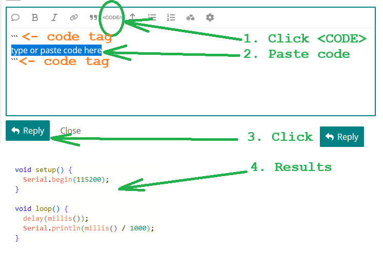
A screenshot of a code editor interface with green arrows and numbered steps illustrating how to insert and execute code using the `` tag. |
https://forum.arduino.cc/t/1458089/2 | |
|
A screenshot of the Arduino IDE displaying C++ code for an Arduino Giga R1, with a compilation error in the output console indicating that the file 'HID.h' could not be found. | https://forum.arduino.cc/t/1458087/1 | |
|
A black remote control featuring a numeric keypad, directional buttons, and colored function keys is resting on a dark surface. | https://forum.arduino.cc/t/1457842/10 | |
|
A wooden box containing various electronic components, including a grid of LEDs, an LCD screen, a small solar panel, and two seven-segment displays, arranged on a transparent surface. | https://forum.arduino.cc/t/1457842/10 | |
|
The image displays a technical table titled "Table 105. 14-bit ADC1 characteristics" that lists various parameters, symbols, conditions, and their corresponding minimum, typical, and maximum values for an analog-to-digital converter. | https://forum.arduino.cc/t/1458079/1 | |
|
A blue USB Host Shield PCB featuring a central microcontroller, multiple integrated circuits, a micro-USB port, a reset button, and various labeled pin headers and components. | https://forum.arduino.cc/t/1458058/2 | |
|
A dark-themed web interface for an Arduino Power Controller (ASCOM) displays eight toggle switches, with Switch 0 and Switch 5 currently set to ON and the others to OFF. | https://forum.arduino.cc/t/1458063/1 | |
|
A screenshot of a Tera Term terminal window displaying boot logs and system information for an ESP32-based device, including SPI flash details, memory addresses, and geolocation data for Paris, France. | https://forum.arduino.cc/t/1458048/1 | |
|
A screenshot of a text document outlining a three-step workaround for the Arduino IDE, which includes quitting the application, deleting the "User data" folder on Windows, Linux, or macOS, and restarting the IDE to apply changes to the `boards.txt` file. | https://forum.arduino.cc/t/1457996/6 | |
|
A screenshot of the GitHub repository for the Arduino-DCF77 library, showing the file directory and a dropdown menu with the 'Download ZIP' option highlighted. | https://forum.arduino.cc/t/1457824/17 | |
|
A blue 5V 8-channel relay module featuring eight blue Song Chong relays, black optocouplers, and terminal blocks on a printed circuit board. | https://forum.arduino.cc/t/1457958/8 | |
|
A section from the InvenSense MPU-6000/MPU-6050 Product Specification document, detailing the electrical and other common specifications for the temperature sensor, including its range, sensitivity, temperature offset, and linearity under specified conditions. | https://forum.arduino.cc/t/1458004/4 | |
|
A screenshot of the InvenSense MPU-6500 Product Specification document, displaying the A.C. Electrical Characteristics table for supplies and temperature sensor parameters. | https://forum.arduino.cc/t/1458004/4 | |
|
A printed circuit board (PCB) layout diagram showing red and blue copper traces connecting components including an Arduino Nano, a CSS Motor Driver V1, a 24-9V DCDC converter, an IMC2209 motor driver, and various labeled input/output terminals. | https://forum.arduino.cc/t/1457407/25 | |
|
A printed circuit board (PCB) layout diagram showing red and blue copper traces connecting components including an Arduino Nano, a CSS Motor Driver V1, a 24-9V DCDC converter, an IMC2209 motor driver, and various labeled input/output terminals. | https://forum.arduino.cc/t/1457407/24 | |
|
A blue 5V 8-channel relay module featuring eight blue Song Chong relays, black optocouplers, and terminal blocks on a printed circuit board. | https://forum.arduino.cc/t/563058/2152 | |
|
A text log displaying repeated entries for iteration 58, each showing a wiper value of 0 and an incident light value alternating between 5.5650 and 5.5640. | https://forum.arduino.cc/t/1458006/1 | |
|
A list of various microcontroller and single-board computer options, including Arduino Mega 2560, Arduino Nano, Arduino Uno, ESP32 DevKit, ESP8266 NodeMCU, Raspberry Pi, Raspberry Pi Pico, Raspberry Pi Zero, Teensy, and Wemos D1 Mini. | https://forum.arduino.cc/t/1456958/7 | |
|
A computer screen displays two instances of the Arduino IDE, with the left window showing C++ code for a DCF77 time library and the right window containing a sketch for an Arduino UNO that processes time data and outputs it to the serial monitor. | https://forum.arduino.cc/t/1457824/11 | |
|
A diagram illustrating a data transmission system where three solar-powered sensor nodes communicate via LoRa to a central microcontroller, which then connects through Ethernet to a router and the internet, ultimately sending data to Weathercloud and OVH. | https://forum.arduino.cc/t/1457823/13 | |
|
A technical diagram illustrating the pin connections for RGB LEDs on a QRB STM development board, distinguishing between those connected to the MPU and those connected to the MCU. | https://forum.arduino.cc/t/1457982/1 | |
|
Several electronic relay modules, some loose and some in anti-static bags, are arranged on a green surface. | https://forum.arduino.cc/t/563058/2150 |