All my arduinos are suddenly blowing up?

DISCLAIMER: I've got a couple of real Arduinos but for prototyping sketchy stuff I use knock-offs for this very reason. That also means that the theoretical maximum voltage for powering an Arduino does not apply.

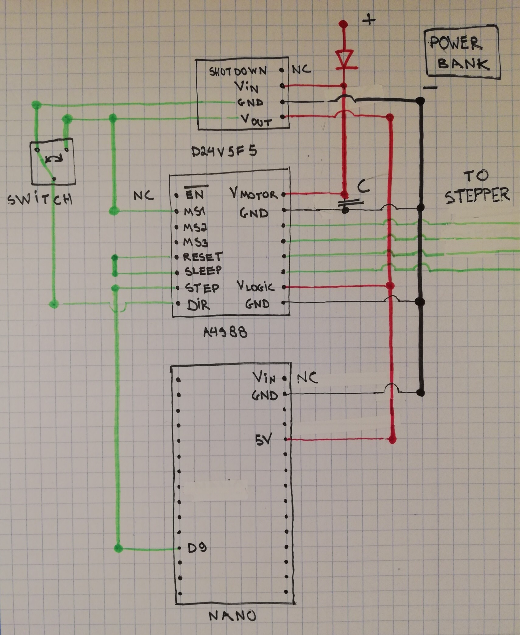
I'm building a barn door tracker and I use an Arduino Nano and a stepper motor. An Arduino should never power a stepper motor directly so I use an A4988 chip. Both the Nano and the stepper motor driver are powered by a 12V power bank.

I do this by sending 12V through the port that says VIN. The driver also gets 12V. All the Nano has to do is send pulses to the driver to tell it when to move the stepper motor by 1 step. For months I've had 0 problems but I just charged my power bank and it's sending 12.4V to the Nano instead of the usual 12.33V when it's not completely full.

My Nano blew up and there is a brown gash on the breadboard.
I measured all the voltages without a motor or Nano connected and then put in a new Nano. Magic smoke ensued and the Nano was dead.

I disconnected everything except the + and - terminal and tried with a new Nano on an empty breadboard. Hissing, smoke, and it died too.

Then I removed the breadboard completely. I measured the power bank voltage for the 5th time and connected Nano to the power bank directly with 2 wires. The Nano smoked and died.

At this point, I messed up big time. I wanted to test if I could power a new Nano with my PC USB port but I plugged in an old broken one. Errors and scary warning messages beeps and hoops all around. I disconnected it instantly and restarted my PC and all seems fine for now. Dumbest thing I did today.

Yesterday I had never broken an Arduino, today I blew up 5. Never had any problems before powering it in exactly the same way.

My best guess is that the voltage converter in the Arduino has to work too hard and I just got reeaaally lucky before. Today my luck ran out. Is this accurate?

Today I read on the forums that the VIN pint is mostly cosmetic and is not meant as a serious way to power a Nano. I'm going to take this into the woods so I have no power grid or PC nearby. What should I do instead? Do I need to step down the voltage to 9V with some kind of buck converter that already has short circuit protection? My power bank also has a 5V 2A output in USB form so I could also power my Nano that way. Is this also an option?

The voltage regulator on most Arduinos is very limited and best not used at all. Use a good quality step down converter to produce 5V for the Arduino and feed it in the 5V pin, as well as the 5V pin on the motor driver (if required).

Make sure that you use secure screw connectors, or solder the connections from the motor windings to the motor driver board. DO NOT use a breadboard for motor connections, as the tracks will burn!

Loose motor connections generate very high voltage spikes that destroy things like Arduinos and motor drivers.

Would adding 3 diodes to step down the voltage before it enters the VIN pin help? I want to use my tracker to photograph comet NEOWISE. https://www.instagram.com/p/CCjhxcMJd2M/ After I get my pictures I can work on a new enclosure, voltage step-down, circuit, cooling solution etc etc for a better design. Atm my main priority is to stop blowing everything up.

Would adding 3 diodes

Probably not.

Man that is 12V going into a 5V board. I don't think you should be putting that much power into it. What I do is I get a 9v battery and get a voltage regulator(5v) on a small perf board and hook that up to the vin.

Snizce:
Man that is 12V going into a 5V board. I don't think you should be putting that much power into it. What I do is I get a 9v battery and get a voltage regulator(5v) on a small perf board and hook that up to the vin.

And that makes no sense either. Did you mean to say "Vin"?


The clear blunder is not comprehending what the "Vin" or "RAW" terminal is. The regulator on the Arduino UNO/ Nano/ Pro Mini/ Mega2560/ Leonardo/ Pro Micro has very little heatsink, so will not pass very much current (depending on the input voltage and thus, how much voltage it has to drop) before it overheats and (hopefully reversibly) shuts down. It is essentially a novelty provided in the very beginning of the Arduino project when "9V" power packs were common and this was a practical way to power a lone Arduino board for initial demonstration purposes. And even then it was limited because an unloaded 9 V transformer-rectifier-capacitor supply would generally provide over 12 V which the regulator could barely handle.

Nowadays, 5 V regulated switchmode packs are arguably the most readily available in the form of "Phone chargers" and switchmode "buck" regulators to regulate from 12 V are cheap on eBay so these can be fed into the USB connector or (more appropriately) 5 V pin to provide adequate power for most applications. Unfortunately, many tutorials or "instructables" are seriously outdated or misleading and have not been updated to reflect the contemporary situation.

If powering from batteries, as long as the battery pack cannot exceed 5.5 V, this must be connected to the 5 V pin.

jremington:
Probably not.

Snizce:
Man that is 12V going into a 5V board. I don't think you should be putting that much power into it. What I do is I get a 9v battery and get a voltage regulator(5v) on a small perf board and hook that up to the vin.

Paul__B:
And that makes no sense either. Did you mean to say "Vin"?


The clear blunder is not comprehending what the "Vin" or "RAW" terminal is. The regulator on the Arduino UNO/ Nano/ Pro Mini/ Mega2560/ Leonardo/ Pro Micro has very little heatsink, so will not pass very much current (depending on the input voltage and thus, how much voltage it has to drop) before it overheats and (hopefully reversibly) shuts down. It is essentially a novelty provided in the very beginning of the Arduino project when "9V" power packs were common and this was a practical way to power a lone Arduino board for initial demonstration purposes. And even then it was limited because an unloaded 9 V transformer-rectifier-capacitor supply would generally provide over 12 V which the regulator could barely handle.

Nowadays, 5 V regulated switchmode packs are arguably the most readily available in the form of "Phone chargers" and switchmode "buck" regulators to regulate from 12 V are cheap on eBay so these can be fed into the USB connector or (more appropriately) 5 V pin to provide adequate power for most applications. Unfortunately, many tutorials or "instructables" are seriously outdated or misleading and have not been updated to reflect the contemporary situation.

If powering from batteries, as long as the battery pack cannot exceed 5.5 V, this must be connected to the 5 V pin.

I think I got it guys. I just bought this: Pololu 5V, 500mA Step-Down Voltage Regulator D24V5F5 This looks like something that I could connect easily. I don't really care about efficiency because my battery pack has 6Ah but this looks like it's good quality stuff. I'll give an update if my projects succeeds (or after I blow up the next Arduino Nano).

The regulator on the nano is a rice-grain sized piece of garbage at best.

There are lots of things I'm totally comfortable with on clone boards, but trusting that the dirt cheap manufacturer in china used a regulator at least as capable of handling input voltages a few tenths of a volt above the nano's spec'ed maximum is not one of them.

Also, as a point of advice, if you let the smoke out of one board when you connect a new part (the new power bank. in your case), the correct thing to do is say "woah, there's something about this new part that isn't okay here. I don't know why, but I'd better figure it out", not "let me try it again with four more spare boards" Good thing nano clones are cheap!

If the problem was that you were juuust under the voltage that was enough to trash the regulator before, and that 0.07v is enough to push it over the edge, then a trio of diodes in series would totally work. Hell, even ONE diode would - though I would never be comfortable with my supply being within a fraction of a volt away from letting the smoke out of my parts, so I'd reach for 3 too if I was going to do that

A 5v linear regulator would be my first choice, though (be sure to use input and output caps per it's datasheet spec; if it only specs a 0.1uF cap on input, add like a 10uF electrolytic on the input too for board level decoupling - with the 5v regulated output going to the 5v pin (the nano has schottky diode between USB 5v and Vcc, so that's safe). Switch mode converters are great if you care about efficiency, or need significant current, and so on - but the nano itself - assuming there's nothing that's drawing a significant amount of current from the 5v rail (which I'm pretty confident is the case, since there's no way that regulator could have powered much of anything with 12v input before), I default linear regulators - they're dirt cheap, dead simple, and you can build them from parts rather than having to buy assembled modules.

That all aside, this raises some read flags for me. I would be really surprised if that measly 70mV was enough to make the difference between "works long term" and "fails instantly", and do so consistently among 5 boards with may well have different provenance.... Are you sure nothing else was connected incorrectly? You didn't reverse the polarity accidentally by any chance did you? Because THAT will trash things instantly, and the nanos are NOT protected against that.

Another brief aside - the only board I've smoked in over a year was a nano clone. That schottky diode I mentioned in series with USB power is so wimpy that - unlike most boards, where a short on USB power will just result in the computer turning off the port, the diode will burn out instead. I get away with shorting USB serial adapters out constantly :stuck_out_tongue:

DrAzzy:
The regulator on the nano is a rice-grain sized piece of garbage at best.

:o

Could be that OP had 5volt power to the Nano from USB, and and un-powered load (motor) on the V-in pin.
Back-powering through a regulator is a great way to kill a regulator. Clone or otherwise.
Leo..

Wawa:
:o

Argh... I was getting it confused with the pro mini, where the regulator is in SOT-23-5... The nano does indeed have a 1117-series reg, which, even with 12v should be able to supply enough current to run a few small connected devices...

Though this confirms my suspicion that it's not the slightly higher voltage... as the 1117-series regulators are all rated for more than 12v (though, due to thermals, not for particularly useful amounts of current)

Hi,
Can you post a circuit diagram of how you had the Nano connected to the motor controller, motor and power supplies?

Thanks.. Tom.. :slight_smile:

DrAzzy:
Also, as a point of advice, if you let the smoke out of one board when you connect a new part (the new power bank. in your case), the correct thing to do is say "woah, there's something about this new part that isn't okay here. I don't know why, but I'd better figure it out", not "let me try it again with four more spare boards" Good thing nano clones are cheap!

I mentioned in my post: "Never had any problems before powering it in exactly the same way."

I've been using the power bank for 6+ months with 0 issues ever on my perfboard in the same configuration.
That's why I didn't suspect it at all during troubleshooting. After I blew a capacitor by connecting the terminals in the wrong way on my perfboard I replaced the capacitor and powered it on again. Nano blew up. So I remade the circuit on a breadboard with new components and tried there. Nano blew up. Then I removed all the chips, it blew up. Then I removed all wires except VIN and GND. And finally the breadboard itself. Then only the power bank was left and I realized the problem. I'm using a 5V stepdown voltage regulator now.

Arduino nano's don't like 12v and this is there MAXIMUM rating. I blew a few up before realizing that the voltage was 12v. I stepped the voltage down to 9 volts and they didn't blow up.

what does your Arduino do when you power them via the USB port?

if they would power up. You could do a loop backtest of your Arduino's. this will test the serial chip.

is it possible that you breadboard is shorted?

All right here's how I wired it up after including a 5V step-down voltage regulator as you guys suggested. I ran a 20-minute stress test with a new Arduino Nano, driver and stepper motor on a new breadboard. No problems at all. The components don't even get warm which is surprising for components that normally run pretty toasty.

Here's the circuit:

Any thoughts?

zwettekop:
Any thoughts?

Can only see parts of the diagram without having to click away advertising (which I won't).
Why don't you post the image here.
Leo..

Here's the circuit