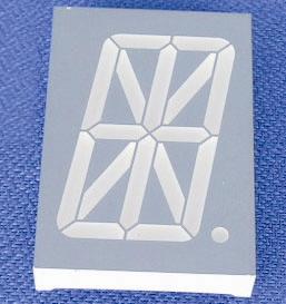
I have an Arduino, that is already in use and integrated into another I want to add something to it. It is an What I want to do is writing some information on a alphanumeric display like this one for example http://www.allproducts.com/manufacture99/flying/Product-20079259230.jpg. The more Letters and Numbers I can write at once the better.
The problem is, since the Arduino is already in use there are only few pins left:
Pin 5 / T1
GND
+5V
PIN 19 ADC 5
PIN 7
PIN 6
TX
RX
I so far understood, that you can save a lot of pins using the serial pins. But how? The link "Serial" in the reference section does not help me a lot. The examples there do not even use the serial pins TX and RX :o
Is there an understandable explanation out there for the use of serial ports?
Serial means different things. The RX and TX pins are tied to a uart that handles a LOT of overhead but they are tied to the USB-Serial chip and normally can't be used. Any other digital pins can be used to drive the shift register which will drive the display. For other devices you can use SPI, I2C or software serial and other pins.
There are serial LCDs that have a device to accept serial data. You need a datasheet for any device so you can match it up with the right library or create on.
Thats because the Rx and Tx pins are RS-232 serial, and that is a specific protocol to created long long time ago and was made to use in teletypes and the like, read more about it in the wikipedia, and usually serial lcd's or serial other things use i2c or spi serial protocols that are different from what the Rx and Tx pins can generate as they are connected to the usart of the atmega used in the arduino and they can only behave as GPIO or as RS-232 serial
No that is not true. The RS232 standard refers to the type of connector, the pin out of it and the voltage levels used to carry the logic information. The Rx and Tx pins are asynchronous serial format at TTL levels. To convert this to RS232 you need a driver chip that converts a logic one to -12V and a logic zero to +12V.
This thing is creazy. How could you use 3 pins for the 7 that are normally needed :-? Anyway I will try to implement it, before I understand it all
But I have one question before I start:
In the above example there is a display used with 1 line and 24 columns. In this turorial (Arduino Tutorial - connecting a parallel LCD) it is said: The good news is that all of these displays are 'swappable' - if you build your project with one you can unplug it and use another size. Your code may have to adjust to the larger size but at least the wiring is the same!
Does that mean, that I could simply by another LCD Display for example with 2 lines 16 columns instead. Nothing of the wireing would be different. And the program I have to write will roughly be the same, exept for the number of lines and columns used.
Right?
This is true. However it has to be the same interface type. Your 3 wire display is a serial interface display, so you can use any larger serial interface LCD display. Most LCDs are of a parallel interface type so you can''t swap between the two types without changing the wiring.
Anyway I will try to implement it, before I understand it all
Good job the inventors of a nuclear power station didn't take that approach.
No that is not true. The RS232 standard refers to the type of connector, the pin out of it and the voltage levels used to carry the logic information. The Rx and Tx pins are asynchronous serial format at TTL levels. To convert this to RS232 you need a driver chip that converts a logic one to -12V and a logic zero to +12V.
I simplified my explanation, i said that so that the OP could see that serial and i2c are different things.
The trick is to simplify without being wrong. I know it is a difficult skill but it is worth pursuing.
My favourite version of simplification to the point of incorrectness is in the English National Curriculum for schools which mandates that you teach the incorrect fact:-
"A day is the length of time it take the Earth to turn once on it's axis"
But I have one question before I start:
In the above example there is a display used with 1 line and 24 columns. In this turorial (Arduino Tutorial - connecting a parallel LCD) it is said: The good news is that all of these displays are 'swappable' - if you build your project with one you can unplug it and use another size. Your code may have to adjust to the larger size but at least the wiring is the same!
Does that mean, that I could simply by another LCD Display for example with 2 lines 16 columns instead. Nothing of the wireing would be different. And the program I have to write will roughly be the same, exept for the number of lines and columns used.
Right?
It looks like no one has answered this question for you.
... if you build your project with one you can unplug it and use another size.
That is correct. All you have to change is the argument (the stuff in parentheses) of the lcd.begin() statement. You may also have to change some of the cursor positioning.
Finally I got it working as it was expected to. And it was much more easy than I thought. The arduino documentation is very good! Thank you very much again.
The problem is, since the Arduino is already in use there are only few pins left:
Pin 5 / T1
GND
+5V
PIN 19 ADC 5
PIN 7
PIN 6
TX
RX
What is keeping you from doing just that?
Make these connections:
LCD <--> Arduino
RS          5
RW          Gnd
E           19
DB4         7
DB5         6
DB6         1 (tx)
DB7         0 (rx)
And implement it with this:
LiquidCrystal lcd(5, 19, 7, 6, 1, 0);
I think principally nothing. I am not clear about what all of this port could do and if I could use them all. For example what does T1 or ADC 5 mean? :-?
But the 3 Pin version has a major advantage: It leaves the tx rx open for other things. I came to arduino over the "mignon game kit". The MGK has the mentioned ports left to be used. With Rx Tx I could connect two MGK and play multiplayer games.
Anyway, I have learned a lot about microcontroller during the last week. Now I stop it for some weeks. It costs tooo much time.