Alternating voltage pulses to a coil

I'm new to Arduino and am working on a clock using an electromagnetic pendulum. The pendulum has a magnet at the bottom and passes over a coil which induces a voltage. When voltage is detected it sends a pulse to the coil which gives the pendulum a nudge. This much works fine. The pendulum length is about 40 inches which results I pulses at 1 second intervals.

My problem is with the other 2 pins connected to both sides of the coil of a quartz clock mechanism. My goal is to alternately pulse the pins mimicking the alternate pulses that a quartz clock produces. I have the pins alternately set high and low hoping to create the pulses I need.

My question is whether I can have the coil connected across the pins and through code have one pin high and the other as ground. Am sitting on a plane right now. I'll send the code when I'm able. Thanks

Your question does not seem to be related to LEDs or multiplexing, which is the forum section you have posted in. Please always read the sticky post at the top of a forum section so you know if it's the right place. I will move your question somewhere more appropriate.

You probably shouldn't connect a coil to the Arduino pins. Two reasons:

First, Arduino pins can only source or sink a max of 40mA. For safety and long life of the Arduino, keep it to no more than 30mA. How much current does your coil draw?

Second, when the current to a coil is switched off, a negative voltage is generated which will damage the Arduino pins. Protection/flyback diodes must be added to protect the arduino pins from these negative voltages.

Maybe if your coil draws less than 30mA and you have added the 4 protection diodes, it might be ok.

If the coil draws more current, you need to use an h,-bridge module or chip. (This module or chip will have the 4 protection diodes built-in).

To recommend an appropriate h-bridge chip/module, you need to tell the forum the voltage and current of the coil. But don't choose L298 or L293 chips/modules. These are a very old design that causes many problems for beginners.

When you can, draw also a schematic. It is not at all clear what exists and how you want to change it.

Pendula with magnetic drive typically employ a simple circuit that gives the nudge you speak of.

I am guessing you want to use the pendulum you have to run a clock that would normally operate from a crystal oscillator driving its own coil/motor.

Guessing, so.

a7

I have clock like that with a replacement mechanism. The clock drives the pendulum,which has ZERO to do with time keeping. The pendulum makes a one cycle per second and the magnetic push is ALWAY the same polarity and the push also is done only once per second, NOT each time the pendulum passes the center point.

At least it does that. I saw one small clock with a pendulum that was close but easily demonstrated to be not one cycle per second.

I was not able to look into what made it keep going.

a7

Here is the clock I am trying to recreate. The author uses a Pickaxe chip and Pickaxe editor to program the chip. I tried to recreate on the Arduino, the basic code he wrote for the pickaxe chip. The pendulum is the time keeper and the goal is to alternately pulse the motor coil of an analog clock.

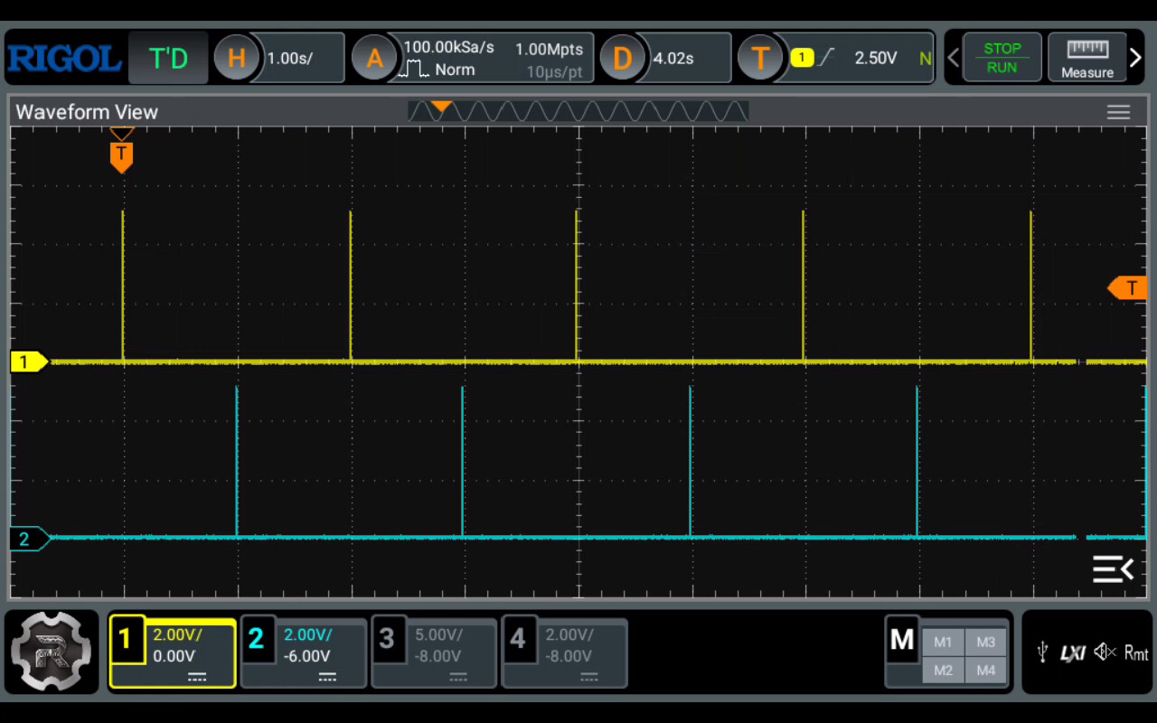
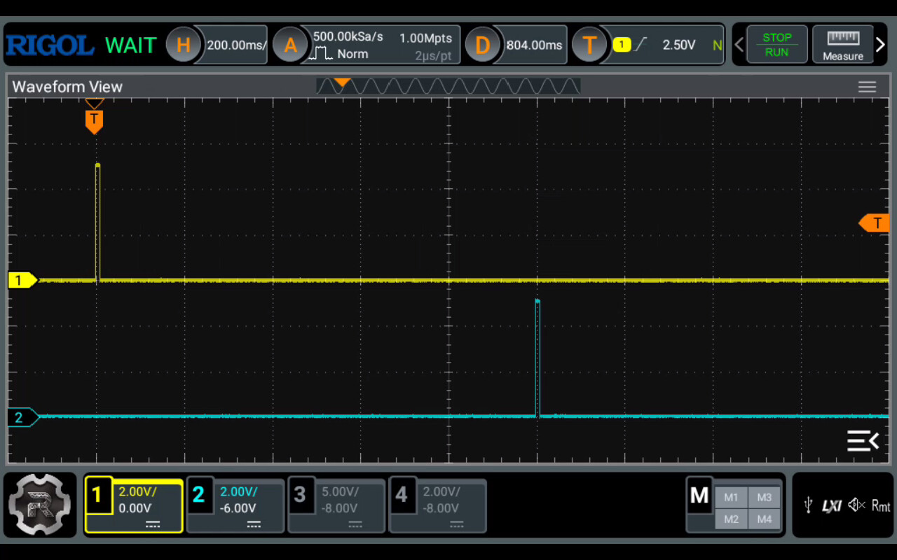
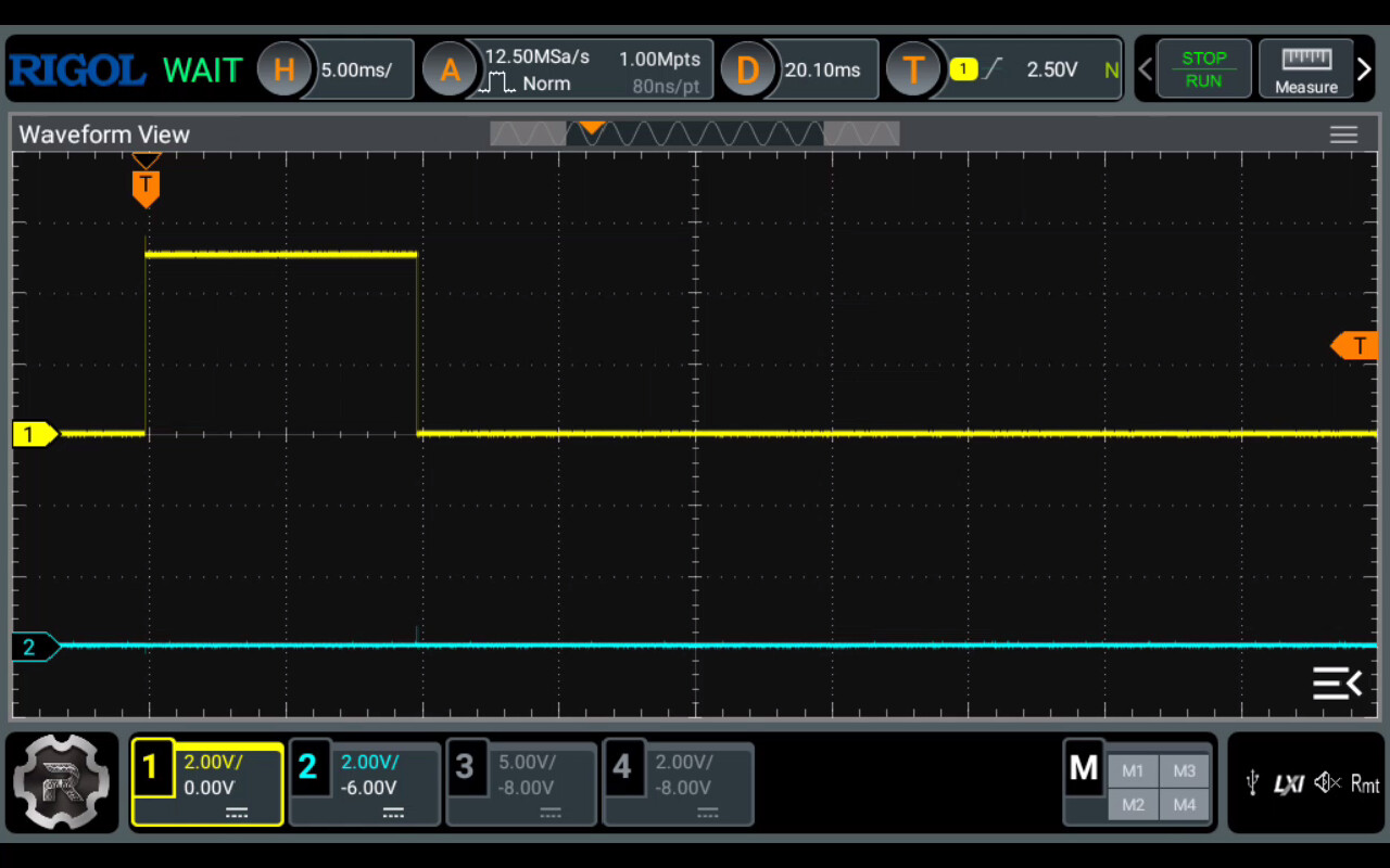
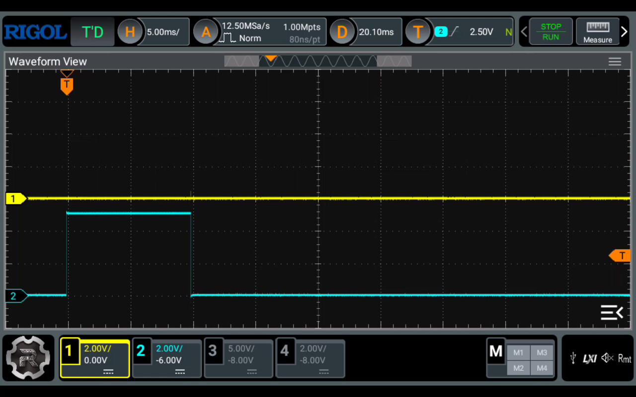
I have the pendulum working nicely but can't seem to get the alternating pulses. I'm using LEDs to observe whether I am getting the alternating pulses and am not getting them. Thanks to all for the help

Here is the code for an Arduino driven analog clock. I'm trying to regulate it with the pendulum circuit.

type or paste code here

Clock Tick Demonstration
//
// By Matt Mets, completed in 2008
//
// This code is released into the public domain. Attribution is appreciated.
//
// This is a demonstration on how to control a cheapo clock mechanism with an Arduino.
// The clock mechanism works by using an electromagnet to pull a little fixed magnet,
// similar to how a DC motor works. To control this with the Arduino, we need to hook a
// wire up to each side of the electromagnet (disconnect the exisiting clock circuity if
// possible). Then, hook each of the wires to pins on the Arduino. I chose pins 2 and 3
// for my circuit. It is also a good idea to put a resistor (I chose 500 ohms) in series
// (between one of the wires and an Arduino pin), which will limit the amount of current
// that is applied. Once the wires are hooked up, you take turns turning on one or the
// other pin momentarily. Each time you do this, the clock 'ticks' and moves forward one
// second. I have provided a doTick() routine to do this automatically, so it just needs
// to be called each time you want the clock to tick.
//

////// Board Setup /////////////////////////////////////////////////////////////////////////
extern unsigned long timer0_overflow_count;

int clockA = 2; // Set these to the pin numbers you have attached the clock wires
int clockB = 3; // to. Order is not important.

int tickPin = clockA; // This keeps track of which clock pin should be fired next.

// Initialize the IO ports
void setup()
{
pinMode(clockA, OUTPUT);
pinMode(clockB, OUTPUT);

digitalWrite(clockA, LOW);
digitalWrite(clockB, LOW);

Serial.begin(9600);
}

// Move the second hand forward one position (one second on the clock face).
void doTick() {

// Energize the electromagnet in the correct direction.
digitalWrite(tickPin, HIGH);
delay(10);
digitalWrite(tickPin, LOW);

// Switch the direction so it will fire in the opposite way next time.
if (tickPin == clockA)
{
tickPin = clockB;
} else {
tickPin = clockA;
}
}

// Main loop
void loop()
{
unsigned long startTime = millis();
unsigned long temp;

// Pretend to be a regular clock, and tick once a second.
while (true)
{
startTime += 1000;

// Wait until a second has passed.  Note that this will do ugly things when millis()
// runs over, so we only have about 9 hours before this version will stop working.
while (startTime - millis() > 0) {}

doTick();

}

Here millis() takes about 49.7 days to run over. And running over doesn't have to be a problem in any case.

Can't you just call doTick() once every pendulum nudge pulse, or every other such pulse I guess?

Here's another clock hack that's fun and informative

a7

The LEDs will only flash for 10ms, this is probably too fast to see.

The code is functioning correctly,

See the oscilloscope traces below:


Timebase 1s/division.


Timebase 200ms/division.


Timebase 5ms/division, Pin 2.


Timebase 5ms/division, Pin 3.

You could try temporarily changing the delay(10) in the function doTick(), to delay(100) to make the flashes of the LED visible for test purposes.

Thanks, really appreciate you trying out the code with an oscilloscope. I'll keep working on it and post my results.

I have an update on my Arduino driven, pendulum regulated clock. I appreciate the help I have received. The code I ended up with an an attempt at a circuit diagram are included below. A couple interesting things:
I started with a pulse of 15 ms but that created wider pendulum swings than I wanted and the clock runs backwards.

I changed the pulse to 12 ms and the clock runs forwards but advances 2 seconds with each ticks.
When the pulse length is shortened to10 ms the clock again runs backwards with one second per tick (Pendulum length gives period of 2 seconds or 1 tick per second)

I may try playing with the code and change the pulse length each tick so we have a "two steps forward and one step back" which might be interesting.

I'd appreciate any thoughts on why the pulse length could be affecting the direction of movement for the clock

int coil=A2;
int coilout=A2;
int b2=0;
int clockA = A3;          // Set these to the pin numbers you have attached the clock wires
int clockB = A4;          // to.  Order is not important.
int tickPin = clockA;
int nolight=13;
void setup() {
  // put your setup code here, to run once:
 pinMode(clockA, OUTPUT);
  pinMode(clockB, OUTPUT);
  pinMode(coil,INPUT);
pinMode(coilout,OUTPUT);
pinMode(nolight,OUTPUT);


}

void loop() {
digitalWrite(nolight,LOW); 
digitalWrite(clockA, LOW);
  digitalWrite(clockB, LOW);
  digitalWrite(coilout,LOW);

 b2=analogRead(coil);
 if (b2>5)
 {digitalWrite(tickPin, HIGH);
 digitalWrite(coilout,HIGH);
  delay(10);//with a delay of 15 ms clock runs backwards
 // at 12 ms clock runs forward but advancing 2 seconds with each tick instead of expected 1 sec
//  10 ms clock runs backwards again with 1 sec\tick
 digitalWrite(tickPin, LOW);
  digitalWrite(coilout,LOW);
   if (tickPin == clockA)
  {
    tickPin = clockB;
  } else {
    tickPin = clockA;
   
  }
 delay(600);}
 

}

This topic was automatically closed 180 days after the last reply. New replies are no longer allowed.