I made amplifier with d822 transistor but i can't hear any sound!!

Where did you get that circuit from, post a link.
Can we assume you have provided power, some sort of appropriate input and turnt up the volume? ![]()
How is the Arduino going to be involved?
a7
Are you trying to power a 3W amplifier off the arduino 5V pin ?
FYI, post says 822 but schematic says 882.

1 Like
thanks raschemmel
I will power with external adapter ![]()
and i will send signal through audio connector that made from esp32 board ![]()
I think you changed 10uf capacitor right? I hope this changes work ![]()
l wil test it later cause 4am here. thanks
really thank you you are the king!
Why? If you want to learning, fine. If you want to use it and it is part of a larger project I prefer a ready amp like PAM8403 for example.
https://www.aliexpress.com/item/32515881989.html
10 PCS under $4 with shipping.
1 Like
That is a "class B" amplifier - not useful for audio.
1 Like
nvm didn’t see which post you replied to
Yeah, class D is fine. I use one to run my stereo speakers.
1 Like
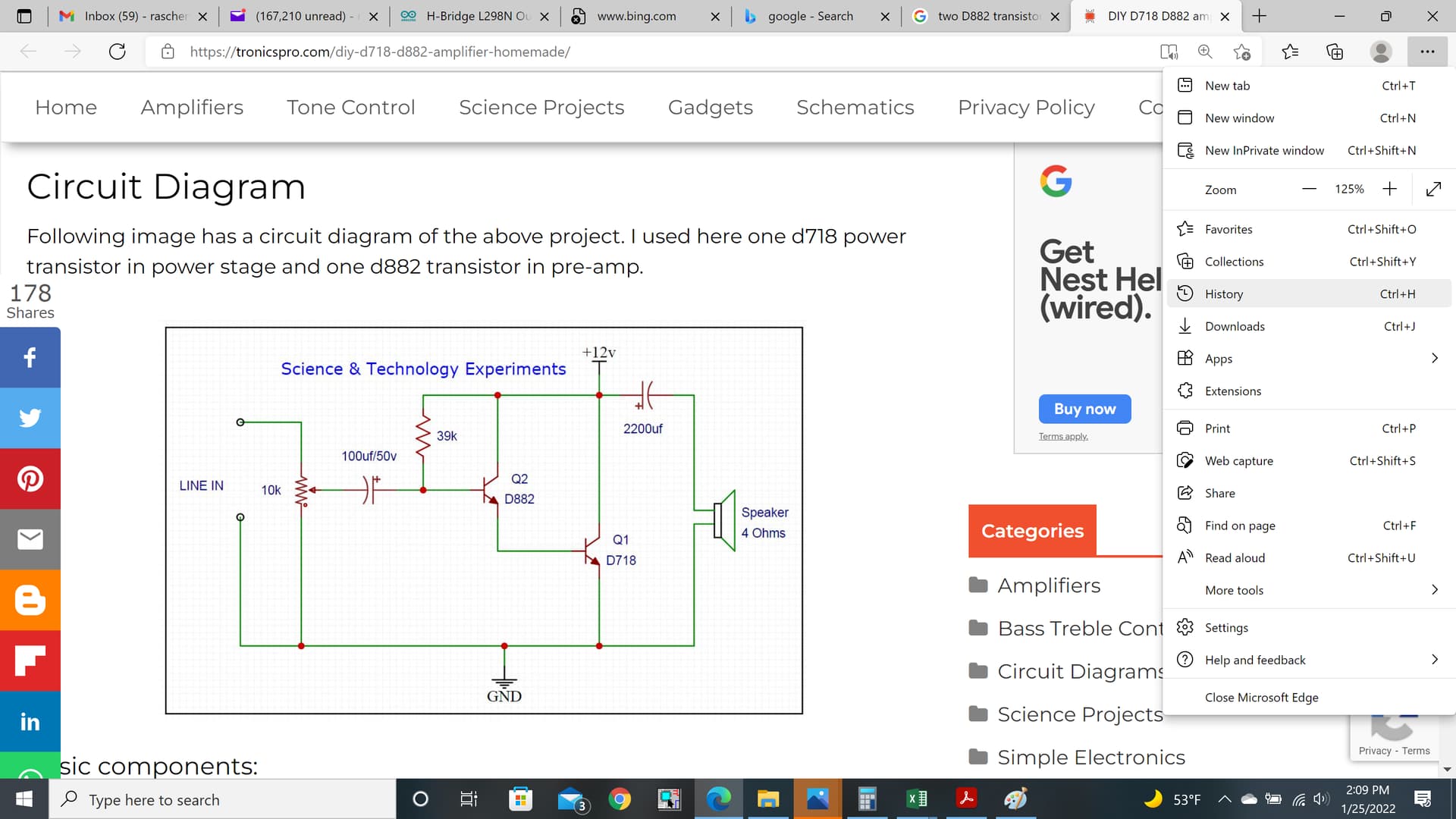
I didn't change anything. I just drew a proper
schematic from what you posted.
Your cap was backwards. The + terminal should towards the input, but I doubt that's why it didn't work. You might try ohming it out per my schematic to see if it matches.
Try this circuit (make sure to heatsink transistors !)
That's as useless as the original posted one ! ![]()
With three modifications ![]()
Drop that crappy design and get a PAM8403.
Leo..
Let's try this again. This amplifier can only work on positive half cycles. So, it lacks the linear response that you need for audio. Actually, it might be class C because the Q1 bias is only 500mV and both Q1 and Q2 emitter base junctions have to be forward biased for Q2 to conduct. That means horribly distorted audio on loud passages, and no audio at all when the level is low.
It kind of amazes me that someone would have the chutzpah to publish stuff like this.
Most likely, the person has no real understanding of the circuit, but it sort of worked. That is enough for some.
I'm probably being really dumb, here, but how can that circuit work at all? All Q1 does is put a variable load across the 12V supply. Nothing there drives the loudspeaker, unless the supply has a high internal impedance so it bounces up and down with the load.
Sure, the circuit in post #9, which is not the same as the OP's circuit, will "work" and produce some sound.
Q1 acts as a switch to charge and discharge the cap through the speaker (meanwhile shorting out the power supply). It really is an idiotic circuit, though, much worse than the OP's.
Yeah, to be honest I didn't do a a sanity check o it because I was pressed for time. I probably shouldn't posted it without proof reading it.
My bad. It does look pretty sketchy.
Good catch though.
Okay, I see your point. I think it would sound obviously broken though... you'd have to have a very tin ear to miss that level of distortion.
Shorting the power supply is certainly a red flag. I should've caught that. I must be getting old...
I thought you were? ![]()
What a dumb circuit, there is even the video of it in action, sounds horrible, all distorted. The author talks specifically of a large heat sink to protect the transistor but doesn’t say anything about what would happen to the power supply if you keep on shorting it, lol