For example, with the code above, I can turn off duty when it is above the 1.1V threshold.
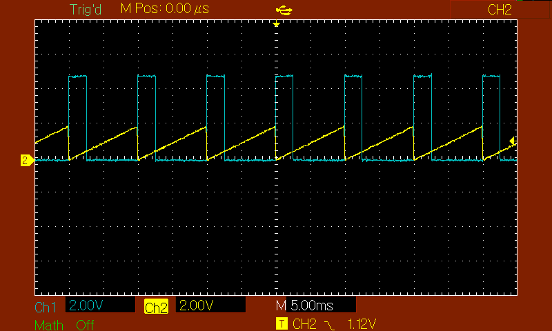
I am adding a visual for the duty I want.
The generated pwm and comparison must be purely hardware.
It seems you're running Timer1 in 9-bit phase correct mode, but you only set OCR1B and don't touch OCR1BL and OCR1BH individually; I'd expect 8-bit PWM resolution would therefore suffice (WGM11 = 0; WGM10 = 1). Anyway, if it works in general, you could also just leave it like it is under the credo 'never change a winning team'
Assuming you're essentially running in 8-bit mode, you'd use OCR1B as the register that controls the PWM duty cycle. So that line where OCR1B is set is where you can start making changes to control the PWM frequency.
What you need to do is make a variable (e.g. a byte/uint8_t) that holds the value you're going to set OCR1B to.
Then separately you'll have to read the ADC pin of your choice in some place. You can do this by adding an ISR for the ADC, or you can simply do it in the loop with a delay (or millis timer) of your choice. In this ADC routine you ultimately set the value of the PWM-value variable based on what you read from the ADC pin.
In that setup you can still use the ACSR check that will set the PWM to a certain value on a compare match of the comparator (i.e. the 'ACSR & (1 << ACO)' part of your code). Whenever that condition holds true OCR1B will be set to 0.
Edit: there was some more rambling about the minimum duty cycle here that only showed I hadn't had enough morning coffee yet - fixing that now!
I am changing my question to
I am generating a pwm using the PWM.h library.
And I am making a comparison using analogComp.h library.
All I want is to turn pwm off and on depending on the comparison result.
For example; A 1V signal is input to the comparator. The threshold I set is 0.5V. When a signal above 0.5V comes, the pwm is turned off. I want it to turn on again when it drops below 0.5V.
#include "analogComp.h"
#include <PWM.h>


void setup() {
    analogComparator.setOn(AIN0, AIN1);
    analogComparator.enableInterrupt(changeStatus, CHANGE);
    InitTimersSafe();
    bool success = SetPinFrequencySafe(10, 20000);
    pwmWrite(10, 127);
}

void loop()
{
  pwmWrite(10, 127);
}

void changeStatus()
{
    pwmWrite(10, 0);
}```


If I do it this way, the pwm duty will be 0 when the threshold is exceeded.
But it works unstable.
I have no experience with those libraries sadly, whenever I do something like this I just manipulate the registers directly. I'm sure the same can be achieved with the libraries you mention, but I'd have to look into it.
What is your hardware setup on the analog pin you use? Do you measure the expected signals there if you use a multimeter?
Btw thanks for the additional explanation; I misunderstood initially, thinking that you wanted a proportional pwm duty cycle to the analog readout and a full-off option using the comparator, but it's only the latter. That makes it easier.
I provide my signals with the signal generator. I'm checking it with an oscilloscope.
I tried to do it directly without using the library but without success.
Is there a sample code for the analog comparator where I can operate on falling edge and rising edge?
void setup() {
  ACSR |= B00010000;      // Clear flag comparator interrupt (ACI bit to 1)
  ACSR &= B11011111;      // Set ACBG, to be equal to "0"
  ADCSRA = (0 && ADEN);   // Disable the ADC module because
  ADCSRB = (1 && ACME);   // Enable the MUX selector for negative input of comparator
  ADMUX = 0;              // Select A0 as comparator negative input
  ACSR |= B00000011;      // Set interrupt on rising edge*/
}

void loop() {
  //Do what you want to do in the loop...
}

// Interrumption vector for the Analog comparator
ISR (ANALOG_COMP_vect) {
  if(ACSR & B00100010)             //If we are into falling edge
  {
    if(!(ACSR & B00100000)) {      //If ACO is 0 (we have that ! for inverse)
      //A change from HIGH to LOW was detected
      //Do what you want to do here...
      ACSR |= B00000011;      // Remember top set back the interrupt on rising edge for next ISR
    }
  }
  else                              //else, if we are into rising edge
  {
    if((ACSR & B00100000)){         //If ACO is 1
      //A change from LOW to HIGH was detected
      //Do what you want to do here...
      ACSR |= B00000010;      // Remember top set back the interrupt on falling edge for next ISR
    }
  }
}
I found such an example, but I can't turn pwm on or off on rising and falling edges.
It's like it doesn't go into cutting at all.
At first glance that code looks like a very reasonable solution. A matter of tracking down why it doesn't work, which seems like a basic debugging job. What I'd do is use some Serial println's in different parts of the ISR to see if it reaches those points when it should. Of course using Serial.print/println in an ISR is bad practice, but for quick testing/debugging purposes it usually works ok-ish, especially if you prevent nested interrupts from occurring.
This part of the code does not work.
Are the configurations wrong?
I input DC 1V from Analog IN --> A0
I'm entering a regulated DC 0-3V on pin number 6
I added Serial.prints in interrupt but is not showing on serial port screen.
I can compare the DC voltages connected to the 6th pin and 7th pin on Arduino and operate with pwm. This code looks fine for now.
There is a problem like this;
If I input a 7.pine Ramp signal and give a DC signal to 6.pine, it cannot turn off the pwm in the parts where the ramp is above the DC reference.
The basis of what I want to do is;
I'm running a track with PWM and reading the current (rapma signal) of that track. If the level of the ramp signal I'm reading is above my reference it should turn off the pwm. It should also open pwm as soon as it's below the reference.
You are not really using PWM in the Arduino sense here.
You can use HW comparator to generate this "PWM". Tou can also use digitalWrite or direct port manipulation in the ISR instead of the PWMWrite. With direct port manipulation it may be a lot faster.