Can an Arduino handle analog impulse signals where the peak voltage is 10V? I have done some research on the forms and found that Arduino's maximum input voltage is 5V but I thought maybe they can handle impulse signals because they do not have much current going through. Like how lightning and sparks both have high voltages, but sparks are harmless due to the low current.
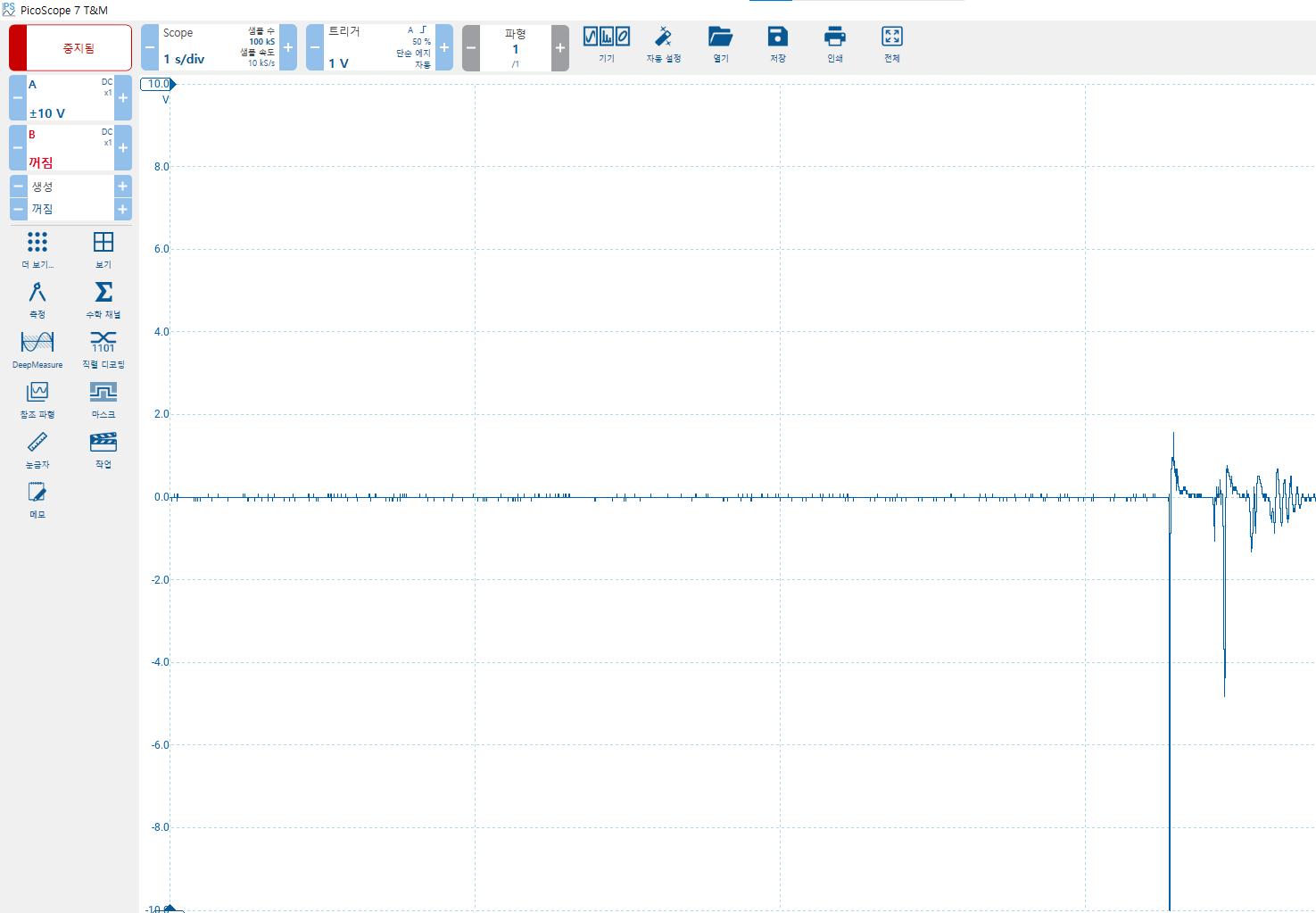
I have attached a picoscope file of the sensor output. You can see that the peak is over 10V, but the duration of the peak is extremely low.
If the Arduino cannot handle such signals, what kind of microcontroller board or SBC would be suitable for such sensors?
No, you should never expose any microprocessor input to more than 5volt (3.3volt for the newer 3.3volt-logic processors). And the peaks are negative, so 0.3volt is the limit there for all processors.
There are solutions, like voltage dividers and/or clamping diodes.
To advise you there, we have to know what are you measuring.
Leo..
If there's actually something limiting the current, right. The voltage will drop (Ohm's Law) and the high voltage won't exist..
A 10K series resistor may be enough to protect the Arduino because the "regular" Arduino (ATmega chip) has "small" protection diodes on the inputs connected to Vcc and ground so when you go about 0.5V above Vcc, or about 0.5V negative, those diodes conduct, limiting the voltage. But I believe they are only rated for 1mA.
Or, here some external protection circuits. (You can increase the current limiting resistor to 1K or more.)
P.S.
You'll probably need to use trigger an interrupt with the pulse because otherwise it's unlikely that you'll be reading the input pin at the same instant as the pulse.
It takes about 0.1ms for an analogRead, so the pulse must stay at it's maximum for that time.
Assuming you're interested in the peak voltage of the pulse.
Leo..
I have a hydrostatic sensor that outputs 0-10v. I used to divide that with 2*10k resistors and measure the voltage across one of them with the Arduino, a 4.7v zenner diode across the input pins was used to protect against over voltage. I wasn’t interested in reading to the full 100% potential of the hydrostatic or I would have used mismatched resistors so my zenner would not clip the higher range.
I have now realised I only need to read the lower 20% of the range so I put the 0-10 straight to the Arduino and use a 10k resistor in series for current limiting, and retain the zenner in case of start up voltage spikes.
Better remove that too. Max pin voltage is not 5volt, but "VCC+0.3volt", which makes the zener useless when the Arduino happens to be off (VCC= 0volt).
Best protection is the 10k series resistor you talk about, and two Schottky diodes (1N5819 etc).
One from pin to ground and one from pin to VCC (5volt).
Google "clamping diodes" (images) for examples.
Leo..
I leave the Arduino powered 24/7 and only pull a relay to power the hydrostatic once a day at midnight for sampling. That powering up causes a voltage spike. It works so no point changing it. I am however, here to learn better ways of doing these things in future.
You didn't give me much to work with, but the spike could be caused by the wiring inductance between sensor and Arduino pin. Try a 100n cap between pin and ground, close to the Arduino pin. That will most likely kill the spike, without effecting sensor readings.
Leo..
Well I have had a few measures of red wine at this time of Saturday so don’t expect total sense from my end. I don’t know if there is a spike but it seemed prudent to clamp V-in to 4.7 in case when the pins are only 5 volt tolerant (5.3 I have learned). I only ever see upto 1.3v when sampling. I could sample 24/7 but it’s just trending oil levels in my tank kerosine tank and once a day is plenty. I planning to get a 16 bit ADC shield this summer for better resolution,
I will be more than interested I. Improving the set up at that point so any suggestions are gratefully received.
The sensor is a FMX2 0-10bar Endress +Hausserr water pilot, I use a signal conditioner to convert its 4-20mA output to 0-10v. I had them to hand. If I was buying parts I would have selected a water pilot that read 0-2 meters because my tank is less than 2m deep. If I recall the signal conditioner is Marposs branded, I wouldn’t be willing to put money on it without checking.
And yes, I know water pilot suggests water, mine has worked fine in oil for a few years all the same. Specific gravity or kerosine is 0.8 and water is 0.981 so you just have to change the calibration ratio.
It seems that an FMX21 has a 4-20mA output, in which case you shouldn't use default (5volt) Aref. A 51 ohm sense resistor with the Uno switched to 1.1volt Aref could be more stable.
But your sensor might not have a 4-20mA output. Sensors like that also come in 0-10volt.
0-10volt output sensors are also better measured with Aref switched to internal.
Only sensors with ratiometric outputs should be used with default (5volt) Aref.
If your sensor is 4-20mA or 0-10volt, then an ADS1115 could improve resolution.
Don't use that solution (or any 16-bit shield) for sensors with ratiometric outputs.
Leo..
Thanks for the reply.
My project is running well, has been for a good while. I am not the original poster but am still interested in the alternative diodes to clamp Vin that you mention. Can you tell me more about those please?
In the early days my readings could be erratic because my Arduino controls 4 different tasks that are independent of each other. I decided to use my Fluke meter to graph Vcc at the Arduino and found it to be inconsistent. As Vcc dropped, due to other tasks creating a varying load, the reading to from my hydrostatic sensor would rise as expected.
I looked in the Atmel data sheet and changed the 2 bits in the Aref register to use pin 21 (I think) as the reference voltage and this settled my reedings out perfectly, I feed 3v into pin 21 from my PSU that powers the hydrostatic sensor, again I used a resistance network to get this voltage.
It may not be the way you would recommend but it works, I would 100% like to learn better solutions moving forward. I intend using a 16 bit ADC to get greater resolution all the same. My power supply is an Omron 2.5A switch mode rail mounted unit, very stable.
I’ll do a paper schematic later today, I’m out and about at the moment.
I use a Fluke 233 multimeter by the way. And a Fluke 323 clamp meter for larger current measurements.
I also have access to an 8 channel scope that prints to paper, it’s about 40 years old but works great for slower rate of change recordings. For live monitoring I use an RSPro 2 channel scope. Both of these belong to a friend so I borrow when needed.
Not only is it over 10V it is also negaive, a double whammy for any microcontroller.
You will need to do some analog conditioning of that signal before you can do any processing with a microcontroller.
Exactly what about the signal are you trying to measure?
That's one part of the mystery solved. You seems to have a sensor with a voltage output (0-10volt).
Those sensors can't be used with Arduino's default Aref.
Next mystery is which Arduino you're using. I guess a Mega, because you talk about pin 21 and 5volt pins. All this information should have been in the first post. Read this (click).
If it's a Mega, you could have dial down sensor voltage to 2.56volt, because a Mega has a 2.56volt internal Aref for absolute voltage sensors.
Leo..
There’s no mystery. It’s a 0-10v output halved with resisters to analog input A2. It has worked flawlessly for a few years now. I don’t use an arduino as such it’s an Atmel328 soldered into a PCB board. Pin 21 is the Atmel PIN number. As I’m sure you’re aware the Atmel328 is used on the UNO.
My Aref input is a set 3v.
It would have been hard for the guy to put this info in the first post, I doubt he had a clue about my set up.