I'm not familiar with these kinds of sensors, but this can't be right, you're just shorting out the transformer.
From what I've read in the datasheet, it seems to me that the input and output are the same. That is: the load is in series with the sensor. This means that when the sensor is off, current flows from live to neutral through the load and through the sensor. The current is too low for the load to turn on, but enough for the sensor itself. When the sensor is activated, the two wires are connected internally, meaning that a higher current flows, turning on the load. There is however, a voltage drop (this is the voltage needed for the sensor to operate).
This means that you always have to have a load connected in order for it to work (the datasheet specifies a minimum current of 5mA).
Please, someone, back me up, or correct me if I'm wrong.
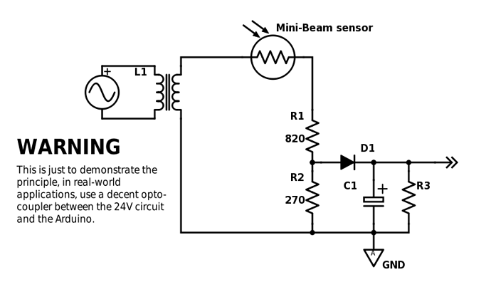
Let's say you have a 1K resistor as a load. This would mean that there would be a voltage drop across it of almost 0V when the sensor is off, and a voltage drop of ~14VAC when on, with a current of ~15mA (see datasheet p.6).
The peak voltage is VRMS√2 = (24-10)V√2 = 19.8V. To get a voltage of ~5Vpeak, you'll need a resistor divider of 820Ω and 270Ω. This is approximately 1KΩ of series resistance.
Then just use a diode and maybe a cap to get DC, and connect it to the Arduino. If the transformer is decoupled (i.e. no connection to mains or earth) you could just connect one end of the voltage divider to the Arduino's ground, it would be safer, however, to use an opto-coupler.
Here's a quick and dirty draft. I have absolutely no idea if it's correct.
C1 and R3 are optional.
DrDiettrich:
You better hire some electronic professional for your project :-]
That's probably the best advice I can give you as well ...
Pieter
