Yes, the green pcb needs two gnd pins for the three pedals. My idea of the circuit has not changed since I originally hand drew them. One of the gnd pins is not working.
What are the results of doing the test in post 52?
Which G pin?????
Or the one in post 38 ?
@camsysca @b707 I am going to leave it to my two friends as I am old and tired.
I want to mention though that using gas, brake, clutch is not only not helpful, it's downright confusing.
This issue involves a G, 3.3V and an analogue pin. That is IT.
Sorry Bob, I didn't know you were still here.
I'm sorry, I was just trying to refer to the ports on the drawing I attached.
A3, A4, and A5 do not read the pentiometer when I press the male connecter to the sides of the hole. Is this something that needs to be soldered to test?
Did you change the pin number in the analogRead() call in the code?
Yes.
You have to solder them.
I'll do that. Thank you.
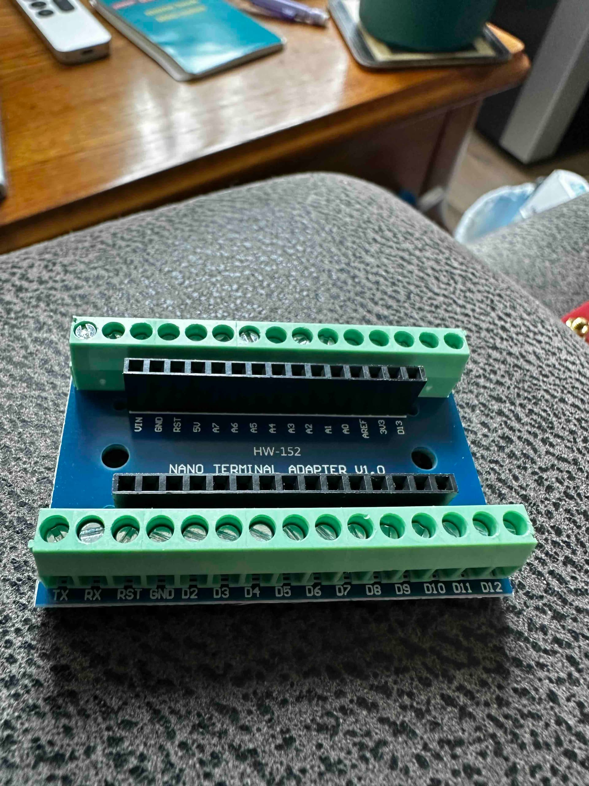
Here are some ways (there are more most cheaper) to mount an Arduino.
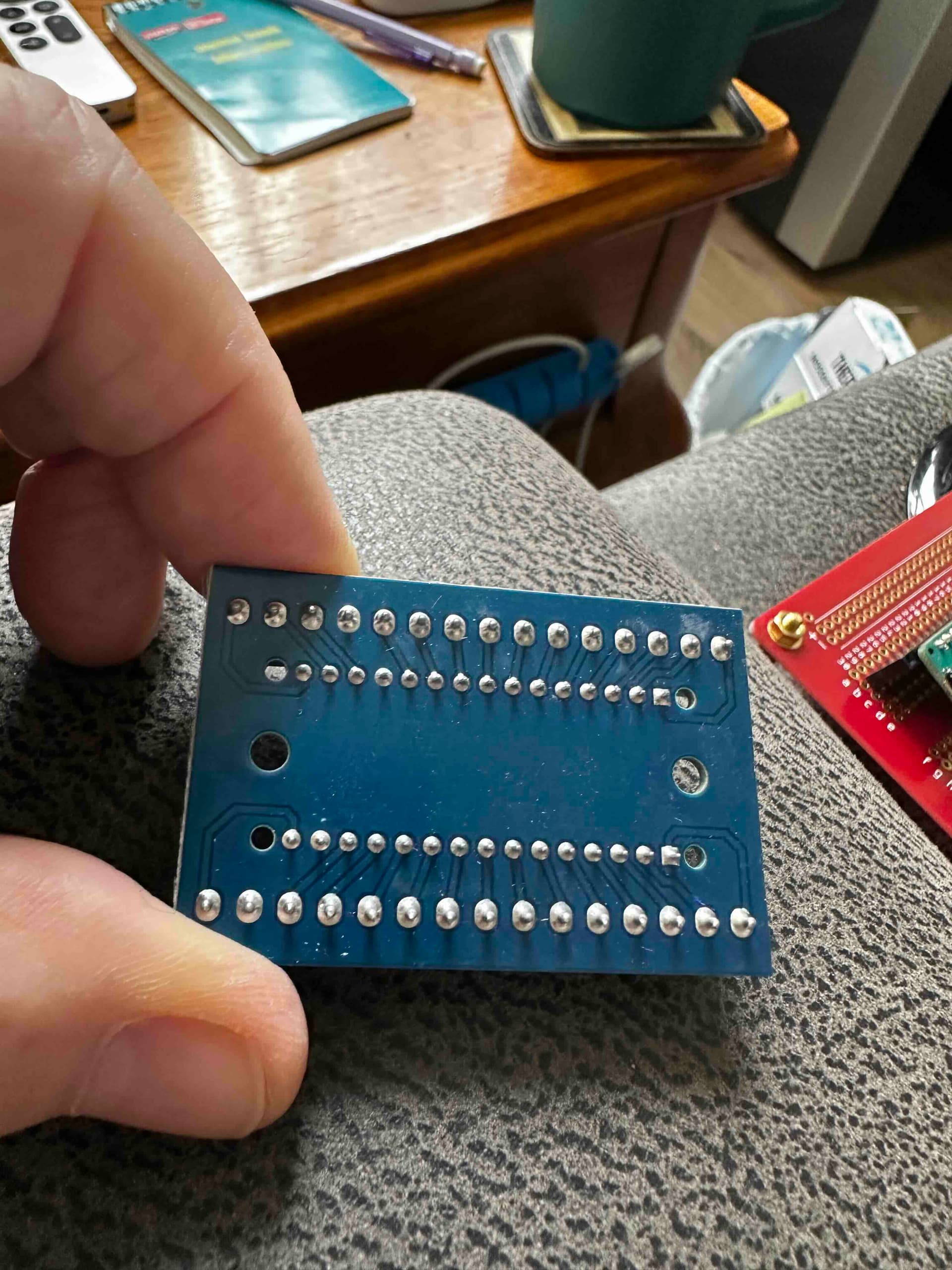
The first one is an off the shelf type. Just plug in the board, then insert bare wires into the screw connectors. NOTE protect the back from shorting, I work on a rubber pad.
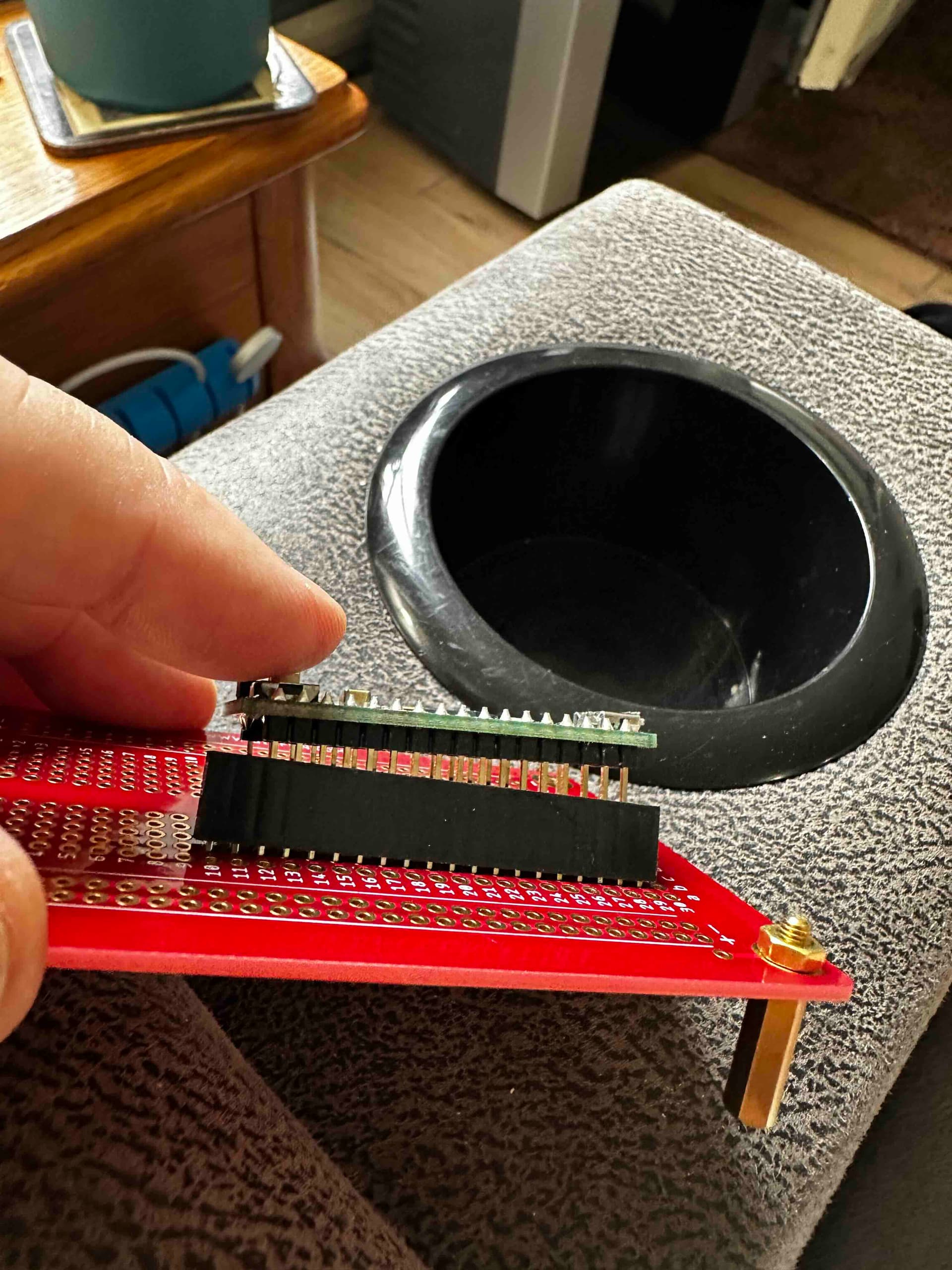
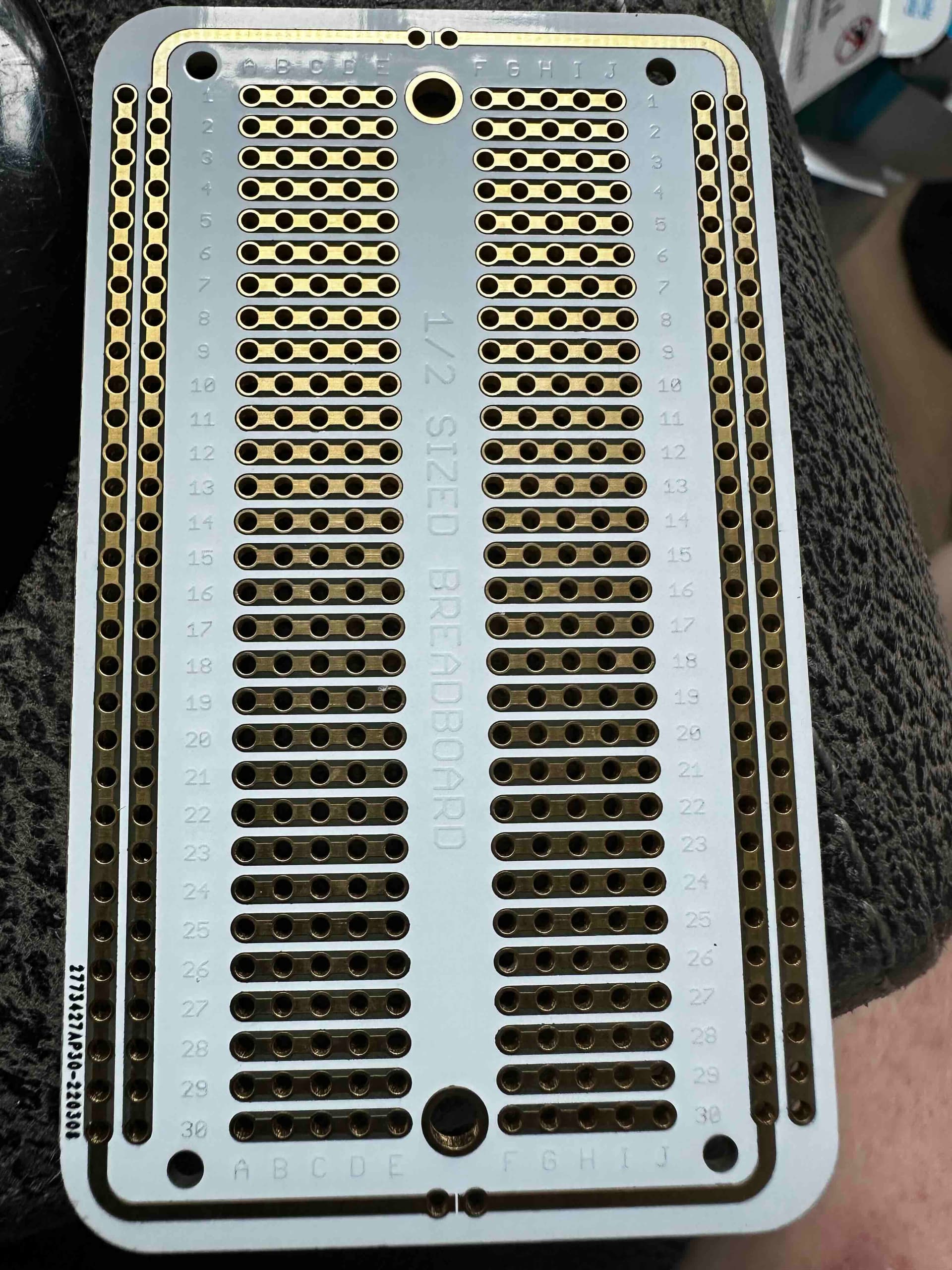
Here is breadboard type proto board. I attached a brass stand off you can get plastic and both in different lengths. To make connections from the board to something you can double the female hdrs and plug in dupont wires, or if permanent solder in the bare wire. This board the holes are not connected, I have others that are just like a breadboard. Lot's of solutions. The worst possible is soldering directly to the Arduino.

That is a lifesaver. So much easier than soldering each pin individually.
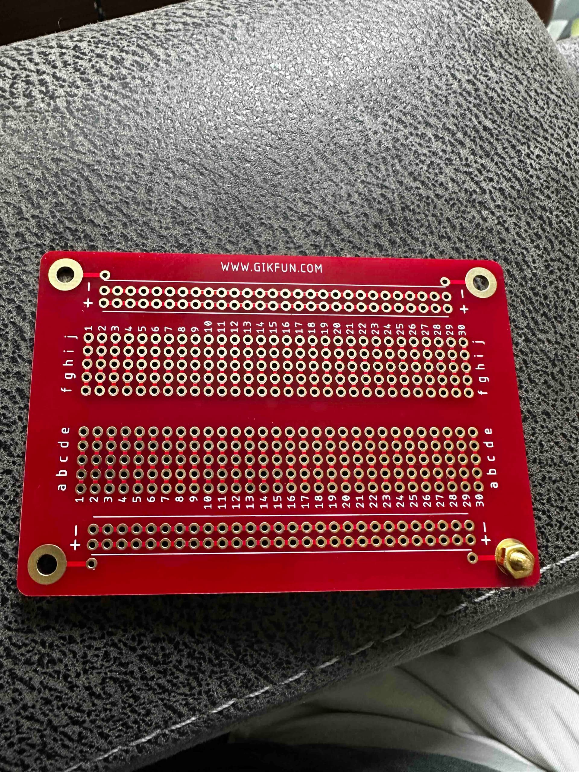
This one is a little harder, still a lot better.
That one is a little big but it'd still work.
You have 3 very anxious helpers waiting to hear the results of the little test.
I did have to leave home and I do have to order parts, but I will definitely get back to all of you. Thank you everyone for the help.