AnalogRead Voltage Issues

Hi

I have a 328P on my own PCB, with its Vcc connected to a boost converter (3.3v out) and ADC1 connected to the middle of a voltage divider between Ground and the solar voltage input to the boost converter.

The PCB layout and schematic are attached.

Using a multimeter I can see 1.1v at AREF, and I can see ~0.4v at ADC1 if I power the PCB from 1 x AA and ~0.9v if I power the PCB from 2 x 1.5v batteries

However, both analogRead and my manual reading of ADCW seem to be giving spurious results. The first reading is very high, but I can live with that, and then subsequently the readings seem to show no relation to the voltage being measured.

I have two copies of the same PCB and both are showing the same problem.

PCB1, 1.5v, output: 545, 539, 521

Setup()
544
545
1023
1023
1023
1023
1023
1023
, Volt: 26, rawVolt: 3433
554
539
1023
1023
1023
1023
1023
1023
, Volt: 24, rawVolt: 3169
536
521
1023
1023
1023
1023
1023
1023
, Volt: 24, rawVolt: 3171

PCB1, 3v, output:1002, 569, 529

Setup()
785
1002
1023
1023
1023
1023
1023
1023
, Volt: 33, rawVolt: 4362
582
569
1023
1023
1023
1023
1023
1023
, Volt: 24, rawVolt: 3170
544
529
1023
1023
1023
1023
1023
1023

PCB2, 1.5v, output:963, 468, 453

Setup()
979
963
1012
1023
1023
1023
1023
1023
, Volt: 26, rawVolt: 3433
514
468
515
1023
1023
1023
1023
1023
, Volt: 24, rawVolt: 3178
501
453
505
1023
1023
1023
1023
1023

PCB2, 3v, output: 1023, 513, 490

Setup()
927
1023
1023
1023
1023
1023
1023
1023
, Volt: 33, rawVolt: 4424
557
513
562
1023
1023
1023
1023
1023
, Volt: 24, rawVolt: 3228
541
490
541
1023
1023
1023
1023
1023

Code:

#include <SoftwareSerial.h> 
SoftwareSerial Serial1(7, 6); // RX, TX

void setup() {
  Serial1.begin(19200);
  Serial1.println("");
  Serial1.println("Setup() "); Serial1.flush();
 }

#define TEMP_OFFSET    32900L // 329.00
#define TEMP_DIV       122L   // 1.22

void loop() {

  analogReference(INTERNAL);
  delay(20);
  Serial1.println(analogRead(A0));
  Serial1.println(analogRead(A1)); // SolarV
  Serial1.println(analogRead(A2));
  Serial1.println(analogRead(A3)); // connected to Vcc
  Serial1.println(analogRead(A4));
  Serial1.println(analogRead(A5));
  Serial1.println(analogRead(A6));
  Serial1.println(analogRead(A7));
  delay(10000);
  
  // Usefull info:  https://garretlab.web.fc2.com/en/arduino/inside/hardware/arduino/avr/cores/arduino/wiring_analog.c/analogRead.html

  // * Read Temperature
  // Temp is coded in the range 0..89, representing -50C to +39C with a resolution of 1C
  //int16_t rawTemp, temp = 0; // use 16bit as ADCW is 16 bit
  
  // The ADMUX(ADC Multiplexer Selection Register) controls the reference voltage, 
  // the presentation of the ADC conversion(left adjust or right adjust) and analog channel selection.
  //ADMUX = (_BV(REFS1) | _BV(REFS0) | _BV(MUX3));  // REFS1 + REFS0 = internal ref (1.1v), MUX3 = A8 = temp
  
  // The ADCSRA (ADC Control and Status Register A) is a register to control AD conversion.
  //ADCSRA |= _BV(ADEN); // ADEN = enable
    
  //delay(20); // wait for voltages to become stable
  //ADCSRA |= _BV(ADSC); // Start the A2D conversion

  //while (bit_is_set(ADCSRA, ADSC));  // ADSC within ADCSRA is cleared when the conversion finishes
  
  //rawTemp = ADCW;
  //temp = ((rawTemp * 100l) - TEMP_OFFSET) / TEMP_DIV;  // ADCW 16 bit reg to degrees Celsius.  100l included to allow integer maths

  //if (temp < -50) temp = -50;  // protect the encoding code
  //if (temp > 39) temp = 39;

  //temp = temp + 50; // scale -50 to 39, to 0 to 89, representing -50C to 39C


  // * Read Solar Voltage
  // Solar volt is coded in the range 0..39, representing 0.0v to 3.9v with a resolution of 0.1v
  uint16_t rawVolt, volt; // use 16bit as ADCW is 16 bit
  rawVolt = 0;

  // The ADMUX(ADC Multiplexer Selection Register) controls the reference voltage, 
  // the presentation of the ADC conversion(left adjust or right adjust) and analog channel selection.
  ADMUX = (_BV(REFS1) | _BV(REFS0) | _BV(MUX1));   // REFS1 + REFS0 = internal ref (1.1v), MUX1 = A1

  for(int i = 0; i <= 5; i++) {  
    // The ADCSRA (ADC Control and Status Register A) is a register to control AD conversion.
    ADCSRA |= _BV(ADEN); // ADEN = enable
    delay(20); // wait for voltages to become stable
    ADCSRA |= _BV(ADSC); // Start the A2D conversion
    while (bit_is_set(ADCSRA, ADSC));  // ADSC within ADCSRA is cleared when the conversion finishes
    rawVolt += ADCW;
  }
  volt = rawVolt / 5; // average across 5 readings

  volt = volt * 0.0381; // scale 0 to 1023 to 0 to 39, representing 0 to 3.9v
  if (volt > 39) volt = 39; // protect the encoding code
  

  //Serial1.print("Temp: ");
  //Serial1.print(temp);
  //Serial1.print(", rawTemp: ");
  //Serial1.print(rawTemp);
  Serial1.print(", Volt: ");
  Serial1.print(volt);
  Serial1.print(", rawVolt: ");
  Serial1.println(rawVolt);
  
  delay(1000);

}

Any thoughts or help appreciated.

Thanks very much
Kevin
I modified the code a bit to just print out the 3 different options for A1: 1) AnalogRead(A1), 3) ADCW * 5 and 2) ADCW * 5 converted into volts * 10. Letting this run for a while I got some interesting results:

3v solarVolts:

Setup()
analogRead(A1): 1023, Volt: 39, rawVolt: 6138
analogRead(A1): 946, Volt: 39, rawVolt: 5769
analogRead(A1): 807, Volt: 37, rawVolt: 4916
analogRead(A1): 706, Volt: 32, rawVolt: 4290
analogRead(A1): 633, Volt: 29, rawVolt: 3832
analogRead(A1): 584, Volt: 26, rawVolt: 3521
analogRead(A1): 544, Volt: 25, rawVolt: 3324
analogRead(A1): 525, Volt: 24, rawVolt: 3212
analogRead(A1): 509, Volt: 23, rawVolt: 3120
analogRead(A1): 500, Volt: 23, rawVolt: 3074
analogRead(A1): 496, Volt: 23, rawVolt: 3024
analogRead(A1): 494, Volt: 22, rawVolt: 2998
analogRead(A1): 492, Volt: 22, rawVolt: 3001
analogRead(A1): 492, Volt: 22, rawVolt: 2991
analogRead(A1): 495, Volt: 22, rawVolt: 2986
analogRead(A1): 492, Volt: 22, rawVolt: 2977
analogRead(A1): 495, Volt: 22, rawVolt: 2994

1.5v solarVolts:

Setup()
analogRead(A1): 1023, Volt: 39, rawVolt: 6138
analogRead(A1): 933, Volt: 39, rawVolt: 5708
analogRead(A1): 792, Volt: 36, rawVolt: 4809
analogRead(A1): 684, Volt: 31, rawVolt: 4143
analogRead(A1): 604, Volt: 27, rawVolt: 3672
analogRead(A1): 549, Volt: 25, rawVolt: 3337
analogRead(A1): 513, Volt: 23, rawVolt: 3126
analogRead(A1): 489, Volt: 22, rawVolt: 2976
analogRead(A1): 475, Volt: 22, rawVolt: 2899
analogRead(A1): 465, Volt: 21, rawVolt: 2838
analogRead(A1): 461, Volt: 21, rawVolt: 2813
analogRead(A1): 457, Volt: 21, rawVolt: 2782
analogRead(A1): 455, Volt: 21, rawVolt: 2777
analogRead(A1): 453, Volt: 21, rawVolt: 2761
analogRead(A1): 453, Volt: 21, rawVolt: 2766
analogRead(A1): 451, Volt: 20, rawVolt: 2751
analogRead(A1): 449, Volt: 20, rawVolt: 2742
analogRead(A1): 450, Volt: 20, rawVolt: 2749
analogRead(A1): 448, Volt: 20, rawVolt: 2740
analogRead(A1): 449, Volt: 20, rawVolt: 2740
analogRead(A1): 447, Volt: 20, rawVolt: 2736

and the simplified code:

#include <SoftwareSerial.h> 
SoftwareSerial Serial1(7, 6); // RX, TX

void setup() {
  Serial1.begin(19200);
  Serial1.println("");
  Serial1.println("Setup() "); Serial1.flush();
 }


void loop() {

  analogReference(INTERNAL);
  Serial1.print("analogRead(A1): ");
  delay(20);
  Serial1.print(analogRead(A1)); // SolarV
  
  // Usefull info:  https://garretlab.web.fc2.com/en/arduino/inside/hardware/arduino/avr/cores/arduino/wiring_analog.c/analogRead.html

    
  // * Read Solar Voltage
  // Solar volt is coded in the range 0..39, representing 0.0v to 3.9v with a resolution of 0.1v
  uint16_t rawVolt, volt; // use 16bit as ADCW is 16 bit
  rawVolt = 0;

  // The ADMUX(ADC Multiplexer Selection Register) controls the reference voltage, 
  // the presentation of the ADC conversion(left adjust or right adjust) and analog channel selection.
  ADMUX = (_BV(REFS1) | _BV(REFS0) | _BV(MUX1));   // REFS1 + REFS0 = internal ref (1.1v), MUX1 = A1

  for(uint8_t i = 0; i <= 5; i++) {  
    // The ADCSRA (ADC Control and Status Register A) is a register to control AD conversion.
    ADCSRA |= _BV(ADEN); // ADEN = enable
    delay(20); // wait for voltages to become stable
    ADCSRA |= _BV(ADSC); // Start the A2D conversion
    while (bit_is_set(ADCSRA, ADSC));  // ADSC within ADCSRA is cleared when the conversion finishes
    rawVolt += ADCW;
  }
  volt = rawVolt / 5; // average across 5 readings

  volt = volt * 0.0381; // scale 0 to 1023 to 0 to 39, representing 0 to 3.9v
  if (volt > 39) volt = 39; // protect the encoding code
  

  Serial1.print(", Volt: ");
  Serial1.print(volt);
  Serial1.print(", rawVolt: ");
  Serial1.println(rawVolt);
  
  delay(1000);

}

Thanks very much
Kevin

Quickly switching between pins as you do might lead to inconsistent results if there is a large difference of voltage between two consecutive pins as there is only 1 ADC attached to the multiplexed entries

  Serial1.println(analogRead(A0));
  Serial1.println(analogRead(A1)); // SolarV
  Serial1.println(analogRead(A2));
  Serial1.println(analogRead(A3)); // connected to Vcc
  Serial1.println(analogRead(A4));
  Serial1.println(analogRead(A5));
  Serial1.println(analogRead(A6));
  Serial1.println(analogRead(A7));

Usually one reads the pin once, throw away that value, and read it again.

J-M-L:
Quickly switching between pins as you do might lead to inconsistent results if there is a large difference of voltage between two consecutive pins as there is only 1 ADC attached to the multiplexed entries

Thanks JML, So I modified the code to throw away the first read and to increase the delay, results are still very similar though, switching between 3v and 1.5v input each time you see 'Setup()':

Setup()
analogRead(A1): 560, Volt: 27, rawVolt: 3579
analogRead(A1): 548, Volt: 26, rawVolt: 3426
analogRead(A1): 542, Volt: 25, rawVolt: 3340
analogRead(A1): 536, Volt: 24, rawVolt: 3279
analogRead(A1): 531, Volt: 24, rawVolt: 3253
analogRead(A1): 526, Volt: 24, rawVolt: 3188
analogRead(A1): 522, Volt: 24, rawVolt: 3224
analogRead(A1): 513, Volt: 24, rawVolt: 3228
analogRead(A1): 525, Volt: 24, rawVolt: 3168
analogRead(A1): 510, Volt: 24, rawVolt: 3215

Setup()
analogRead(A1): 1002, Volt: 39, rawVolt: 6138
analogRead(A1): 883, Volt: 39, rawVolt: 5346
analogRead(A1): 738, Volt: 33, rawVolt: 4449
analogRead(A1): 634, Volt: 29, rawVolt: 3849
analogRead(A1): 567, Volt: 26, rawVolt: 3460
analogRead(A1): 526, Volt: 24, rawVolt: 3227
analogRead(A1): 502, Volt: 23, rawVolt: 3093
analogRead(A1): 488, Volt: 22, rawVolt: 3015
analogRead(A1): 481, Volt: 22, rawVolt: 2973
analogRead(A1): 476, Volt: 22, rawVolt: 2943
analogRead(A1): 474, Volt: 22, rawVolt: 2931
analogRead(A1): 472, Volt: 22, rawVolt: 2924
analogRead(A1): 471, Volt: 22, rawVolt: 2914
analogRead(A1): 470, Volt: 22, rawVolt: 2913

Setup()
analogRead(A1): 1006, Volt: 39, rawVolt: 6138
analogRead(A1): 894, Volt: 39, rawVolt: 5423
analogRead(A1): 754, Volt: 34, rawVolt: 4551
analogRead(A1): 653, Volt: 30, rawVolt: 4003
analogRead(A1): 594, Volt: 28, rawVolt: 3678
analogRead(A1): 563, Volt: 26, rawVolt: 3421
analogRead(A1): 545, Volt: 25, rawVolt: 3314
analogRead(A1): 517, Volt: 24, rawVolt: 3218
analogRead(A1): 519, Volt: 24, rawVolt: 3210
analogRead(A1): 512, Volt: 24, rawVolt: 3225
analogRead(A1): 508, Volt: 24, rawVolt: 3163
analogRead(A1): 512, Volt: 24, rawVolt: 3170
analogRead(A1): 517, Volt: 23, rawVolt: 3143
analogRead(A1): 517, Volt: 24, rawVolt: 3161
analogRead(A1): 517, Volt: 23, rawVolt: 3148
analogRead(A1): 513, Volt: 23, rawVolt: 3117

Setup()
analogRead(A1): 1004, Volt: 39, rawVolt: 6138
analogRead(A1): 883, Volt: 39, rawVolt: 5342
analogRead(A1): 735, Volt: 33, rawVolt: 4434
analogRead(A1): 631, Volt: 29, rawVolt: 3829
analogRead(A1): 563, Volt: 26, rawVolt: 3442
analogRead(A1): 522, Volt: 24, rawVolt: 3204
analogRead(A1): 498, Volt: 23, rawVolt: 3067
analogRead(A1): 485, Volt: 22, rawVolt: 2991
analogRead(A1): 477, Volt: 22, rawVolt: 2947
analogRead(A1): 472, Volt: 22, rawVolt: 2923
analogRead(A1): 470, Volt: 22, rawVolt: 2911
analogRead(A1): 469, Volt: 22, rawVolt: 2904
analogRead(A1): 468, Volt: 22, rawVolt: 2898
analogRead(A1): 468, Volt: 22, rawVolt: 2900
analogRead(A1): 468, Volt: 22, rawVolt: 2896
analogRead(A1): 467, Volt: 22, rawVolt: 2894
analogRead(A1): 467, Volt: 22, rawVolt: 2895

Setup()
analogRead(A1): 1007, Volt: 39, rawVolt: 6138
analogRead(A1): 897, Volt: 39, rawVolt: 5406
analogRead(A1): 748, Volt: 34, rawVolt: 4548
analogRead(A1): 656, Volt: 30, rawVolt: 3958
analogRead(A1): 591, Volt: 27, rawVolt: 3596
analogRead(A1): 562, Volt: 25, rawVolt: 3382
analogRead(A1): 531, Volt: 24, rawVolt: 3254
analogRead(A1): 523, Volt: 24, rawVolt: 3211
analogRead(A1): 519, Volt: 24, rawVolt: 3196
analogRead(A1): 506, Volt: 24, rawVolt: 3156
analogRead(A1): 517, Volt: 24, rawVolt: 3173
analogRead(A1): 514, Volt: 23, rawVolt: 3117
analogRead(A1): 505, Volt: 23, rawVolt: 3138
analogRead(A1): 517, Volt: 23, rawVolt: 3145
analogRead(A1): 513, Volt: 23, rawVolt: 3127
analogRead(A1): 518, Volt: 23, rawVolt: 3125
analogRead(A1): 512, Volt: 23, rawVolt: 3142
analogRead(A1): 510, Volt: 24, rawVolt: 3156
analogRead(A1): 507, Volt: 24, rawVolt: 3162
analogRead(A1): 501, Volt: 23, rawVolt: 3131
analogRead(A1): 515, Volt: 23, rawVolt: 3130
analogRead(A1): 505, Volt: 24, rawVolt: 3152
analogRead(A1): 506, Volt: 24, rawVolt: 3170
analogRead(A1): 505, Volt: 23, rawVolt: 3127

Setup()
analogRead(A1): 1003, Volt: 39, rawVolt: 6138
analogRead(A1): 879, Volt: 39, rawVolt: 5322
analogRead(A1): 731, Volt: 33, rawVolt: 4406
analogRead(A1): 626, Volt: 28, rawVolt: 3797
analogRead(A1): 558, Volt: 25, rawVolt: 3410
analogRead(A1): 518, Volt: 24, rawVolt: 3177
analogRead(A1): 494, Volt: 23, rawVolt: 3042
analogRead(A1): 481, Volt: 22, rawVolt: 2968
analogRead(A1): 473, Volt: 22, rawVolt: 2928
analogRead(A1): 469, Volt: 22, rawVolt: 2904
analogRead(A1): 467, Volt: 22, rawVolt: 2893
analogRead(A1): 465, Volt: 21, rawVolt: 2881
analogRead(A1): 464, Volt: 21, rawVolt: 2878
analogRead(A1): 464, Volt: 21, rawVolt: 2875
analogRead(A1): 463, Volt: 21, rawVolt: 2871
analogRead(A1): 462, Volt: 21, rawVolt: 2865

Setup()
analogRead(A1): 1010, Volt: 39, rawVolt: 6138
analogRead(A1): 895, Volt: 39, rawVolt: 5365
analogRead(A1): 753, Volt: 34, rawVolt: 4488
analogRead(A1): 649, Volt: 29, rawVolt: 3922
analogRead(A1): 582, Volt: 27, rawVolt: 3584
analogRead(A1): 551, Volt: 25, rawVolt: 3383
analogRead(A1): 534, Volt: 25, rawVolt: 3320
analogRead(A1): 526, Volt: 24, rawVolt: 3227
analogRead(A1): 522, Volt: 24, rawVolt: 3229
analogRead(A1): 513, Volt: 24, rawVolt: 3195
analogRead(A1): 510, Volt: 23, rawVolt: 3139
analogRead(A1): 507, Volt: 23, rawVolt: 3118
analogRead(A1): 502, Volt: 24, rawVolt: 3171
analogRead(A1): 508, Volt: 24, rawVolt: 3163
analogRead(A1): 511, Volt: 24, rawVolt: 3178
analogRead(A1): 515, Volt: 24, rawVolt: 3179
analogRead(A1): 509, Volt: 24, rawVolt: 3188

And the code:

#include <SoftwareSerial.h> 
SoftwareSerial Serial1(7, 6); // RX, TX

void setup() {
  Serial1.begin(19200);
  Serial1.println("");
  Serial1.println("Setup() "); Serial1.flush();
 }


void loop() {

  analogReference(INTERNAL);
  Serial1.print("analogRead(A1): ");
  delay(50);
  analogRead(A1); // Throw first measure away
  delay(50);
  Serial1.print(analogRead(A1)); // SolarV
  
  // Usefull info:  https://garretlab.web.fc2.com/en/arduino/inside/hardware/arduino/avr/cores/arduino/wiring_analog.c/analogRead.html


  // * Read Solar Voltage
  // Solar volt is coded in the range 0..39, representing 0.0v to 3.9v with a resolution of 0.1v
  uint16_t rawVolt, volt; // use 16bit as ADCW is 16 bit
  rawVolt = 0;

  // The ADMUX(ADC Multiplexer Selection Register) controls the reference voltage, 
  // the presentation of the ADC conversion(left adjust or right adjust) and analog channel selection.
  ADMUX = (_BV(REFS1) | _BV(REFS0) | _BV(MUX1));   // REFS1 + REFS0 = internal ref (1.1v), MUX1 = A1

  for(uint8_t i = 0; i <= 6; i++) {  // Loop 6 times, throw first measure away
    // The ADCSRA (ADC Control and Status Register A) is a register to control AD conversion.
    ADCSRA |= _BV(ADEN); // ADEN = enable
    delay(50); // wait for voltages to become stable
    ADCSRA |= _BV(ADSC); // Start the A2D conversion
    while (bit_is_set(ADCSRA, ADSC));  // ADSC within ADCSRA is cleared when the conversion finishes
    if (i != 0) rawVolt += ADCW; //throw first measure away
  }
  volt = rawVolt / 5; // average across 5 readings

  volt = volt * 0.0381; // scale 0 to 1023 to 0 to 39, representing 0 to 3.9v
  if (volt > 39) volt = 39; // protect the encoding code
  

  Serial1.print(", Volt: ");
  Serial1.print(volt);
  Serial1.print(", rawVolt: ");
  Serial1.println(rawVolt);
  
  delay(1000);

}

as you don't switch analog pin, there is no reason for the

delay(50); // wait for voltages to become stable

I'm a bit confused in what you do.
what's the clock speed on your board? (you power it with 3.3v right?)

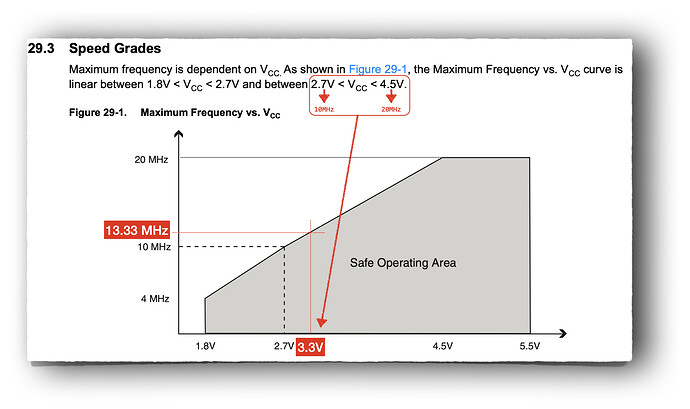
the spec for a 328/P states

Speed Grade:
̶ 0-4MHz@1.8-5.5V, 0-10MHz@2.7-5.5.V, 0-20MHz@4.5-5.5V

and you have a table that shows


so @3.3V you can't run @16Mhz without expecting flaws.
the spec also states

1.1.7 AVCC
AVCC is the supply voltage pin for the A/D converter, PC3:0, and ADC7:6. It should be externally connected to VCC, even if the ADC is not used. If the ADC is used, it should be connected to VCC through a low-pass filter. Note that PC6..4 use digital supply voltage, VCC.

J-M-L:
I'm a bit confused in what you do.
what's the clock speed on your board? (you power it with 3.3v right?)

Hi JML

Yes powered by 3.3v out of the boost converter. Running at 8mhz via a external crystal.

Thanks
Kevin

So it is looking more like a hardware issue, although a couple of differences I can not remove in my test.

I built the circuit on a Seedunio that I had laying around, and with a couple of minor corrections to the code it now works.

To get the environment as similar as possible I have even programmed the Seedunio using ICSP using the same settings as my own hardware.

So the only differences I can not remove between this test hardware and my PCB are: 16Mhz rather than 8Mhz, and the Fuses will be programmed differently.

0v:

Volt: 0, rawVolt: 0
analogRead(A1): 0
0
0
0
0
0
0

3.3v:

analogRead(A1): 876
876
876
876
877
876
876
Volt: 33, rawVolt: 4381
analogRead(A1): 876
876
876
876
876
876
876
Volt: 33, rawVolt: 4380
analogRead(A1): 876
876
876
876
877
876
876
Volt: 33, rawVolt: 4381

and 5v:

Volt: 0, rawVolt: 0
analogRead(A1): 1023
1023
1023
1023
1023
1023
1023
Volt: 39, rawVolt: 5115
analogRead(A1): 1023
1023
1023
1023
1023
1023
1023
Volt: 39, rawVolt: 5115
analogRead(A1): 1023
1023
1023
1023
1023
1023
1023
Volt: 39, rawVolt: 5115

Updated code:

void setup() {
  Serial1.begin(19200);
  Serial1.println("");
  Serial1.println("Setup() "); Serial1.flush();
 }

#define TEMP_OFFSET    32900L // 329.00
#define TEMP_DIV       122L   // 1.22

void loop() {

  analogReference(INTERNAL);
  Serial1.print("analogRead(A1): ");
  delay(20);
  analogRead(A1); // Throw first measure away
  delay(20);
  Serial1.println(analogRead(A1)); // SolarV
  
  // Usefull info:  https://garretlab.web.fc2.com/en/arduino/inside/hardware/arduino/avr/cores/arduino/wiring_analog.c/analogRead.html


  // * Read Solar Voltage
  // Solar volt is coded in the range 0..39, representing 0.0v to 3.9v with a resolution of 0.1v
  uint16_t rawVolt, volt, raw; // use 16bit as ADCW is 16 bit
  rawVolt = 0;

  // The ADMUX(ADC Multiplexer Selection Register) controls the reference voltage, 
  // the presentation of the ADC conversion(left adjust or right adjust) and analog channel selection.
  ADMUX = (_BV(REFS1) | _BV(REFS0) | _BV(MUX0));   // REFS1 + REFS0 = internal ref (1.1v), MUX0 = 1 = A1

  for(uint8_t i = 0; i <= 5; i++) {  // Loop 6 times, throw first measure away
    // The ADCSRA (ADC Control and Status Register A) is a register to control AD conversion.
    ADCSRA |= _BV(ADEN); // ADEN = enable
    delay(20); // wait for voltages to become stable
    ADCSRA |= _BV(ADSC); // Start the A2D conversion
    while (bit_is_set(ADCSRA, ADSC));  // ADSC within ADCSRA is cleared when the conversion finishes
    raw = ADCW;
    Serial1.println(raw);
    if (i != 0) rawVolt += ADCW; //throw first measure away
  }
  volt = rawVolt / 5; // average across 5 readings

  volt = (volt * 0.0381) + 0.5; // scale 0 to 1023 to 0 to 39, representing 0 to 3.9v, +0.5 = round not truncate
  if (volt > 39) volt = 39; // protect the encoding code

  Serial1.print("Volt: ");
  Serial1.print(volt);
  Serial1.print(", rawVolt: ");
  Serial1.println(rawVolt);
  
  delay(1000);

}

when you upload to your PCB, did you choose a platform that is 8MHz ?
do you have a low-pass filter on AVcc ?

for stability you might want also to switch from buck converter to linear regulator