Analog Read weird behavious

Hello,
I am developing a custom board using the Mega2560 chip. and i am stuck reading to analog voltage. One of the voltages is the voltage coming out of a bank of 5 1.5F capacitors (through A1) connected in parallel. These capacitors serve as the source of power for the board and are feed through a screw terminal which will have a solar panel connected to it. Right now I am using a bench power supply. The other one is to measure the voltage of a 12v battery (A2).

The problem is first that no matter what the capacitor voltage is analogRead(A1) reports 514 if the voltage is more than 4.9V and if i Lower the voltage to anything below 4.8 it goes to 512 but it does not move from there.

A2 is even stranger. the actual battery voltage measured with a multimeter is approximately 12.39V. If the source voltage to the board is above 4.8V the analogRead(A2) starts at 380 but it steady declines to lower and lower values ie 200. However, when I lower the supply voltage to the board it immediately starts going up and in a few minutes it can go over 800.

There is no connection between pin A1 and A2. This board is manufactured by jlcpcb and is the second batch that exibits this weird behavious so i have to assume that is not a bad chip and it has something to do with my design. I just can see it.

Here is my code:

#include <Wire.h>
#include <LiquidCrystal_I2C.h>
LiquidCrystal_I2C lcd(0x27, 16, 2);

void setup() {

Serial.begin(9600);
Serial.println(" STARTING" );
lcd.begin();
lcd.backlight();

analogReference(DEFAULT);
}

void loop() {
// put your main code here, to run repeatedly:
int v = analogRead(A1);
delay(100);
Serial.print(" v=" );
Serial.println(v );
int e=analogRead(A2);
lcd.setCursor(0, 1);
lcd.print("C=");
lcd.print(v);

   lcd.print("  E=");
    lcd.print(e);

delay(1000);

}

Here is the part of the design that represents A1

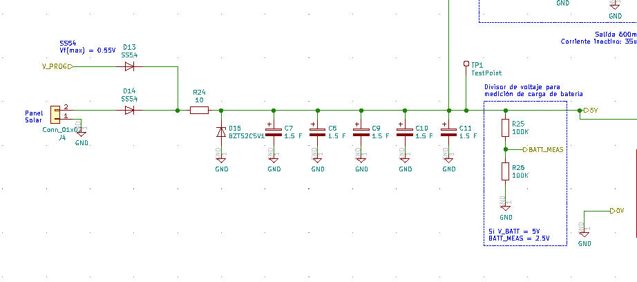
A1 is connected to the label BATT_MEAS

As for A2, here is the design, is a simple voltage divider VEM is connected to A2Screen Shot 2021-10-25 at 10.51.30

Any suggestions would be very much appreciated

The default "5V" ADC reference is Vcc so if Vcc drops your ADC readings increase.

You can use the optional 1.1V internal voltage reference which is very stable and should hold-up as long as there's enough voltage to run the processor. Of course, you'll have to change your 12V voltage divider and add a voltage divider for your 5V measurement.

Although the internal reference is stable, it's not super-accurate so you may have to make a calibration-correction in software if your readings are not accurate enough.

Thanks for the reply. Both analg sources have vltage dividers that allow me to use the INTERNAL2V56 of the mega2560 chip. I just tried by setting

analogReference(INTERNAL2V56)

in the setup and got the same behavour. Alos, the A1 is still stuck at 512 no matter the input voltage.

Any thoughts ?

thanks again

You are indicating that when 0V is applied to the A1, the analog reading produced by the code is 512, correct?

And the issue is when 1/2 of 5V is applied to the A:D converter the readout is 1/2 the A:D converter's full range, right?

Well, the input that A1 is measuring what powers the board so it can not go to 0. However, if using a bench power supply i lower it to 3V the processor is still running but the analogRead(A1) still shows 512. If i bring the power back up to 5 or higher it still stuck at 512.
As you can see in the diagram, the screw terminal feeds into a resistor and a zenner diode with a forward voltage of .9v s it enables me to connect a 6V solar panel. I hava test point right after the capacitors and before the voltage divider and when i measure the voltage of the test point using a multimeter i get values that match what the bench pwer supply is providing (accounting fr the losses in the resistor and the zenner diode).

any thoughst based on this?

thanks again

Hi,
Have you measured the analog port pins with the DMM to check what voltage is actually being presented to the 2560 with respect to the 2560 gnd?

Is this on a breadboard/protoboard or have you got a PCB manufactured?

Thanks.. Tom... :grinning: :+1: :coffee: :australia:

Unfortunately the PCB is manufactured so i dont have access to the pins as such. However, at least for the A1, I do have a test point immediately before the actual voltage divider and when i measure the voltage at the test pint using a multimeter i get 4.72V when the bench power supply is showing 5.9. Given that the zenner diode that is sitting before has a forward volatge drop of .9 its pretty close. Since the voltage divider is made out of 2 100kohm i would expect to see 2.36v at the pin, so i would expect the analogRead function to report 944 instead of 512

Hi,

You cannot put a DMM probe on the connection between R25 and R26 on the PCB?


Can I suggest you drop those values down to 22K each, 100K combination is probably being effected by the input impedance of the analog input.
The diodes D13 and D14 are Schottky diodes not zener diodes.

What is the application?
Any reason that you went straight to PCB instead of making a breadboard prototype to prove the concept?
Can you please post an image of your project and if possible an Exported jpg of the PCB pattern form the CAD used?

Thanks.. Tom... :grinning: :+1: :coffee: :australia:

Why do you have a 3V3 zener? You do realise it will have a significant effect on VEM even below the "breakdown voltage"

Its poor design not to include test points on a custom board. Realistically as its not working right you need to go to breadboard to check your circuit, with an arduino mega.

Hey Tom,
Thanks for the feedback.
I just a DMM probe between r25 and r26 and i Read 2.00V when the power supply is supplying 5v. If i bring the power supply down to 4V I read 1.78V between R25 and R26.
In both cases the analogread still produces 512.

The Zenner diode i was referring is D15. I will replace the 100K to 22K in the next build.
The application is an electric fence monitor. I actuall have tested different parts of the circuit in a breadboard but i needed to put the whole pcb together because the idea of having wires in a breadboard out in the pacdock next to 8000V electric fence seem like a bad idea,

Here is an image of the pcb:

Is that what you mean by an image of the project?

@johnerrington, thanks for the comment, the zenner there is to protect the mcu since i plan to use that part of the circuit to monitor a 12v battery

One more piece of information it just dawn on me that could help solve the mysteryScreen Shot 2021-10-26 at 12.16.38
is that I have AREF tied to VCC

So, if Vcc falls from 5V to 4.5V, VREF will also fall to 4.5V and since the ADC value is the input V (Vcc) compared to VREF (same as Vcc) the ADC value will always be the same. I would use the Mega's internal 2.56V reference and divide your inputs down to less than 2.5V.
Whoops, math typo, I'll be back.
Example: R1 = 10k, R2 = 10k, Vin = 5V, Vout = 5 * 10 / (10 + 10) = 2.5V. ADC value = Vout * 1024 / 2.56 = 1000.
I wonder why the 12V is divided down to 1.8V? R1=15k, R2 = 2.7k would bring 15V down to 2.29V, ADC value, 915.

Using the external voltage reference input pin AREF.

CAUTION: Don't use anything less than 0V or more than 5V for external reference voltage on the AREF pin!

If you're applying an external reference voltage to the AREF pin without a protection resisitor , you must set the analog reference to EXTERNAL before calling analogRead(). Otherwise, you will short together the active reference voltage (internally generated) and the AREF pin, possibly damaging the microcontroller on your Arduino board.

That could make it noisy. The whole point of AREF is to be noise-free and stable, so it has its own decoupling cap and is only connected to AVcc internally via resistance. If AREF varies during a conversion the results may have sparkle codes. You don't want sparkle codes! https://www.analog.com/media/en/training-seminars/tutorials/MT-011.pdf

Normally with very high resolution ADCs great lengths have to be gone to to stabilize the reference voltage, for a low performance ADC a single cap and isolating it from noise sources is usually enough.

@MarkT thanks for that. I have removed the VCC from AREF and just left a 100nF capacitor

This topic was automatically closed 180 days after the last reply. New replies are no longer allowed.