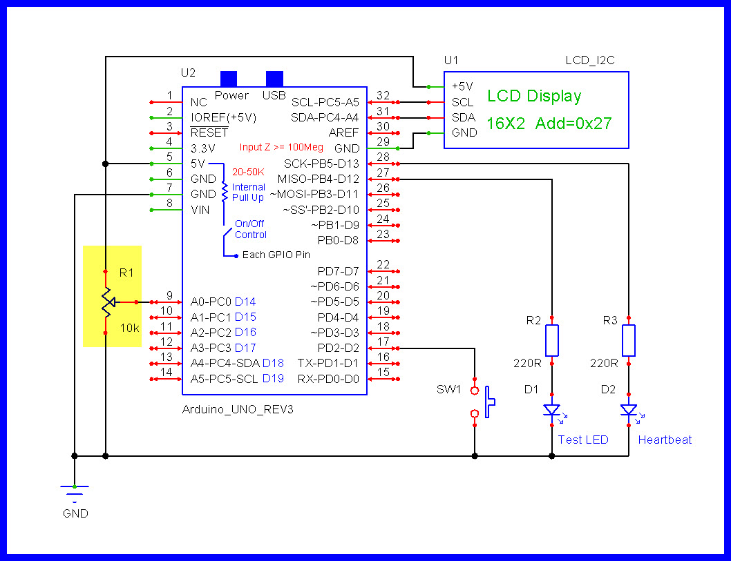
//
//================================================^================================================
//                              B a s i c   L C D   M e n u   S k e t c h
//
//  https://forum.arduino.cc/t/arduino-millis-and-indexing-code/1376338/142
//
//  LarryD
//
//  Version    YY/MM/DD    Comments
//  =======    ========    ========================================================================
//  1.00       25/03/12    Running code
//
//
//
// Notes:
// - The following sketch demonstrates how we can use LCD menus to change program behavior.
//   When you upload the sketch below, the LCD displays a 4-screen menu.
// - Close the switch connected to D02 for 1 second then release.
//   You will see the LED connected to D12 come on for 1 second, then turn off.
// - Tap the switch for less than 150ms seconds.
//   This time the LCD menu will advance to the next screen.
// - Tap the switch 3 more times, the menu will cycle back to the beginning.
// - Advance the LCD menu to Screen 4 by tapping the switch quickly 3 times.
// - "Screen 4" will be on the LCD, hold the switch closed for greater than 3 seconds.
//   The screen will display "LED Interval Updated".
// - Close the switch for 1 second, then release.
//   You will see the LED connected to D12 come on now for 4 seconds, then turn OFF.
//
//
//

//================================================
#include <makeTIMER.h> //makes non-blocking TIMERS
#include <makeInput.h> //makes physical switch objects

#include <Wire.h>

//========================
//Use I2C library:     https://github.com/duinoWitchery/hd44780
//LCD Reference:       https://www.arduino.cc/en/Reference/LiquidCrystal
#include <hd44780.h>   //makes LCD objects, main hd44780 header

//NOTE:
//hd44780_I2Cexp control LCD using I2C I/O expander backpack (PCF8574 or MCP23008)
//hd44780_I2Clcd control LCD with native I2C interface (PCF2116, PCF2119x, etc...)

#include <hd44780ioClass/hd44780_I2Cexp.h> //I2C expander i/o class header

//If you do not know what your I2C address is, first run the "I2C_Scanner" sketch
//OR
//run the "I2CexpDiag" sketch that comes with the hd44780 library
//hd44780_I2Cexp lcd(0x3F);

hd44780_I2Cexp lcd(0x27);


//================================================
#define LEDon              HIGH   //PIN---[220R]---A[LED]K---GND
#define LEDoff             LOW

#define PRESSED            LOW    //+5V---[Internal 50k]---PIN---[Switch]---GND
#define RELEASED           HIGH

#define CLOSED             LOW    //+5V---[Internal 50k]---PIN---[Switch]---GND
#define OPENED             HIGH

#define ENABLED            true
#define DISABLED           false

#define RELAYon            LOW
#define RELAYoff           HIGH

//Atmega 328 UNO, Pro Mini, NANO
#define PULSE62D13         cli(); PINB = bit(PINB5); PINB = bit(PINB5); sei()
#define PULSE126D13        cli(); PINB = bit(PINB5); asm("nop\n"); PINB = bit(PINB5); sei()

//================================================
#define ONE_SECOND         1000ul              //milliseconds
#define ONE_MINUTE         (ONE_SECOND * 60ul) //60 seconds in one minute
#define ONE_HOUR           (ONE_MINUTE * 60ul) //60 minutes in one hour
#define ONE_DAY            (ONE_HOUR * 24ul)   //24 hours in one day


//                                T I M E R   D e f i n i t i o n s
//================================================^================================================
//Notes:
//========================
//data members in class makeTIMER
//.TimerType,   .Interval, .TimerFlag,       .Restart,  .SpeedAdjustPin
//MILLIS/MICROS, 500ul,    ENABLED/DISABLED, YES/NO,    A0-A5
//
//the .SpeedAdjustPin defaults to 0 i.e. no speed adjustment is used
//.SpeedAdjustPin can be = A0-A5, a potentiometer on this pin adjusts the TIMER's speed (used for diagnostics)
//
//class static flag "makeTIMER::normalFlag" can be used to ENABLE/DISABLE adjustable TIMER speed,
//ENABLE (normal speed), DISABLED (a potentiometer on .SpeedAdjustPin controls the TIMER speed)
//
//these are the TIMER functions we can access:
//object.checkTIMER();             - checks to see if the TIMER status: STILLtiming/EXPIRED/TIMERdisabled
//object.enableRestartTIMER();     - enables and restarts the TIMER
//object.restartTIMER()            - restarts the TIMER
//object.disableTIMER();           - disables the TIMER
//object.expireTimer();            - make the TIMER expire
//object.setInterval(100ul);       - set the TIMER interval
//

//========================
makeTIMER heartbeatTIMER =
{
  //.TimerType, .Interval, .TimerFlag, .Restart, .SpeedAdjustPin
  MILLIS, 500ul, ENABLED, YES, 0
};

//========================  (5ms * s_filter) i.e. 5ms * 10 = 50ms for checking a valid switch operation
makeTIMER switchesTIMER =
{
  //.TimerType, .Interval, .TimerFlag, .Restart, .SpeedAdjustPin
  MILLIS, 5ul, ENABLED, YES, 0
};

//========================
makeTIMER machineTIMER =
{
  //.TimerType, .Interval, .TimerFlag, .Restart, .SpeedAdjustPin
  MICROS, 1000ul, ENABLED, YES, 0
};

//========================
makeTIMER commonTIMER =
{
  //.TimerType, .Interval, .TimerFlag, .Restart, .SpeedAdjustPin
  MILLIS, 500ul, DISABLED, NO, 0
};

//========================
makeTIMER testLedTIMER =
{
  //.TimerType, .Interval, .TimerFlag, .Restart, .SpeedAdjustPin
  MILLIS, 1000ul, DISABLED, NO, 0
};


//                                    S t a t e   M a c h i n e
//================================================^================================================
//
//the states in our State Machine
enum STATES : byte
{
  POWERUP, STARTUP, STATE1, WAIT1, STATE2, WAIT2, STATE3, WAIT3, STATE4, WAIT4, FINISHED, UPDATEDmessage
};

STATES mState = POWERUP;


//                              G P I O s   A n d   V a r i a b l e s
//================================================^================================================
//

//Analogs
//================================================
//

//INPUTS
//================================================
//
//We have access to:
//object.validChange()    - checks for a change in state               NOTvalidated(0), VALIDATED(1) or NOchange(2)
//object.pin              - input hardware pin number                  a valid input pin #
//object.lastState        - the state the input was/is in              HIGH/LOW
//object.switchTime       - the millis() value when the switch closes

//========================          GPIO 2
//make the physical switch object
makeInput mySwitch =
{
  //.pin, .lastState
  2, OPENED
};


//OUTPUTS
//================================================
//
const byte testLED                = 12;
const byte heartbeatLED           = 13;

//VARIABLES
//================================================
//
//                                  testLED ON intervals available
//                                     0       1       2       3
unsigned long intervalArray[]     = {1000ul, 2000ul, 3000ul, 4000ul};

//the currentely selected intervalArray item
byte intervalIndex                = 0;

//define our LCD screens
const char* screens[6][2] =
{
  //          111111               111111
  //0123456789012345     0123456789012345     //screenIndex value
  {"    Screen 1    ",  "  Time = 1 sec  "},  //0
  {"    Screen 2    ",  "  Time = 2 sec  "},  //1
  {"    Screen 3    ",  "  Time = 3 sec  "},  //2
  {"    Screen 4    ",  "  Time = 4 sec  "},  //3
  {"  LED Interval  ",  "    Updated!    "},  //4
  {"    Skeleton    ",  "     Sketch     "}   //5
};

//index of the screen now being displayed on the LCD
byte screenIndex                  = 0;

const byte updatedMessageIndex    = 4;
const byte powerUpMessageIndex    = 5;

//Timing Stuff
//========================
const unsigned long shortPushTime = 150ul;  // 0.15 seconds
const unsigned long longPushTime  = 3000ul; // 3 seconds


//                                           s e t u p ( )
//================================================^================================================
//
void setup()
{
  Serial.begin(115200);

  digitalWrite(heartbeatLED, LEDoff);
  pinMode(heartbeatLED, OUTPUT);

  digitalWrite(testLED, LEDoff);
  pinMode(testLED, OUTPUT);

  //================================================
  //LCD stuff
  lcd.begin(16, 2);
  lcd.clear();

  //display the powerup startup message on the LCD
  displayScreen(powerUpMessageIndex);

  //3 seconds to read the updated message
  //set the TIMER interval
  commonTIMER.setInterval(3000ul);

  //start the TIMER
  commonTIMER.enableRestartTIMER();

} //END of   setup()


//                                            l o o p ( )
//================================================^================================================
//
void loop()
{
  //========================================================================
  //Diagnostics:
  //Print the time it takes to return to this same spot.
  //Comment the next 3 lines when no longer needed.
  //static unsigned long startTime;
  //Serial.println(micros() - startTime);
  //startTime = micros();

  //========================================================================
  //Diagnostics:
  //Make a pulse on D13 equal to 62ns or 126ns.
  //PULSE62D13;
  //PULSE126D13;

  //========================================================================  T I M E R  heartbeatLED
  //condition returned: STILLtiming, EXPIRED or TIMERdisabled
  //is it time to toggle the heartbeat LED ?
  if (heartbeatTIMER.checkTIMER() == EXPIRED)
  {
    //toggle the heartbeat LED
    digitalWrite(heartbeatLED, digitalRead(heartbeatLED) == HIGH ? LOW : HIGH);
  }

  //========================================================================  T I M E R  switches
  //condition returned: STILLtiming, EXPIRED or TIMERdisabled
  //is it time to check our switches ?
  if (switchesTIMER.checkTIMER() == EXPIRED)
  {
    checkSwitches();
  }

  //========================================================================  T I M E R  machine
  //condition returned: STILLtiming, EXPIRED or TIMERdisabled
  //is it time to service our State Machine ?
  if (machineTIMER.checkTIMER() == EXPIRED)
  {
    checkMachine();
  }

  //========================================================================  T I M E R  testLed
  //condition returned: STILLtiming, EXPIRED or TIMERdisabled
  //if enabled, is it time to turn OFF the testLED ?
  if (testLedTIMER.checkTIMER() == EXPIRED)
  {
    digitalWrite(testLED, LEDoff);

    //we are finished with this TIMER
    testLedTIMER.disableTIMER();
  }


  //================================================
  //       Other non blocking code goes here
  //================================================


} //END of   loop()


//                                    c h e c k M a c h i n e ( )
//================================================^================================================
//
void checkMachine()
{
  //================================================
  //service the current "state"
  switch (mState)
  {
    //========================
    //this code is run once only at powerup/reset time
    case POWERUP:
      {
        //has the user had enough time to read the power up message ?
        if (commonTIMER.checkTIMER() == EXPIRED)
        {
          //we are finished with this TIMER
          commonTIMER.disableTIMER();

          //next state
          mState = STARTUP;
        }
      }
      break;

    //========================
    case STARTUP:
      {
        //initialize the LCD State Machine
        screenIndex = 0;
        intervalIndex = 0;

        //next state
        mState = STATE1;
      }
      break;

    //========================
    case STATE1:
      {
        //we really should not be using the magic number 0 here as it might change
        //if there is a future screen added, however, for this example we will use 0
        //
        //point to the screen we want displayed
        screenIndex = 0;

        //display the screen
        displayScreen(screenIndex);

        //next state
        mState = WAIT1;
      }
      break;

    //========================
    case WAIT1:
      {
        //stay in this state until the user does something with the mySwitch
      }
      break;

    //========================
    case STATE2:
      {
        //point to the screen we want displayed
        screenIndex = 1;

        //display the screen
        displayScreen(screenIndex);

        //next state
        mState = WAIT2;
      }
      break;

    //========================
    case WAIT2:
      {
        //stay in this state until the user does something with the mySwitch
      }
      break;

    //========================
    case STATE3:
      {
        //point to the screen we want displayed
        screenIndex = 2;

        //display the screen
        displayScreen(screenIndex);

        //next state
        mState = WAIT3;
      }
      break;

    //========================
    case WAIT3:
      {
        //stay in this state until the user does something with the mySwitch
      }
      break;

    //========================
    case STATE4:
      {
        //point to the screen we want displayed
        screenIndex = 3;

        //display the screen
        displayScreen(screenIndex);

        //next state
        mState = WAIT4;
      }
      break;

    //========================
    case WAIT4:
      {
        //stay in this state until the user does something with the mySwitch
      }
      break;

    //========================
    case FINISHED:
      {
        //back to the beginning of the menu screens
        //next state
        mState = STARTUP;
      }
      break;

    //========================
    case UPDATEDmessage:
      {
        //give some time for the user to read the updated message
        //condition returned: STILLtiming, EXPIRED or TIMERdisabled
        if (commonTIMER.checkTIMER() == EXPIRED)
        {
          //we are finished with this TIMER
          commonTIMER.disableTIMER();

          //back to the beginning of the menu screens
          //next state
          mState = STARTUP;
        }
      }
      break;

  } //END of  switch/case

} //END of   checkMachine()


//                                   c h e c k S w i t c h e s ( )
//================================================^================================================
//
//We have access to:
//object.validChange()    - checks to see if there was a valid state change
//object.pin              - input hardware pin number
//object.lastState        - the state the input was/is in
//object.switchTime       - the millis() value when the switch closes

void checkSwitches()
{
  //========================================================================  mySwitch
  //was there a valid change in state for this switch input ?
  //condition returned: NOTvalidated (0), VALIDATED (1) or NOchange (2)
  if (mySwitch.validChange() == VALIDATED)
  {
    //========================
    //was this switch closed ?
    if (mySwitch.lastState == CLOSED)
    {
      //nothing to do here, remember when the switch object closes,
      //we automatically save the time it closed in variable object.switchTime
      //where "object" is the name we gave to this switch
    }

    //========================
    //this switch was opened/released
    else
    {
      //================================================  Short Push
      //proceed to the next screen
      //was this a short push ?
      if (millis() - mySwitch.switchTime <= shortPushTime)
      {
        //we need to "cast" items to prevent compiler warnings
        //advance the State Machine to the next state
        mState = (STATES)((byte)mState + 1);

        //advance the TIMER interval index so it matches the screen being displayed
        intervalIndex++;
      }

      //================================================  Long Push
      //save the new TIMER interval
      //was this a long push ?
      else if (millis() - mySwitch.switchTime >= longPushTime)
      {
        //update the TIMER interval to the new value
        testLedTIMER.setInterval(intervalArray[intervalIndex]);

        //display the updated message on the LCD
        displayScreen(updatedMessageIndex);

        //3 seconds to read the updated message
        //set the TIMER interval
        commonTIMER.setInterval(3000ul);

        //start the TIMER
        commonTIMER.enableRestartTIMER();

        //next state
        mState = UPDATEDmessage;
      }

      //================================================  Regular Push
      //this was a regular push
      //i.e. longer than a short push AND shorter than a long push
      else
      {
        digitalWrite(testLED, LEDon);

        //enable and restart the testLedTIMER
        testLedTIMER.enableRestartTIMER();
      }
    }

  } //END of mySwitch

  //========================================================================  Next Switch

} //END of   checkSwitches()


//                                   d i s p l a y S c r e e n ( )
//================================================^================================================
//
//timing for this function shows about 2.13ms to print two lines of text to a 16X2 LCD
void displayScreen(int index)
{
  static unsigned long startTime;        //               <---------------<<<<<<
  startTime = micros();                  //               <---------------<<<<<<

  lcd.clear();
  lcd.setCursor(0, 0);
  lcd.print(screens[index][0]);
  lcd.setCursor(0, 1);
  lcd.print(screens[index][1]);

  Serial.print(micros() - startTime);   //               <---------------<<<<<<
  Serial.println(" microseconds");      //               <---------------<<<<<<

} //END of   displayScreen()


//================================================^================================================
 .
.