Hi to all friends.
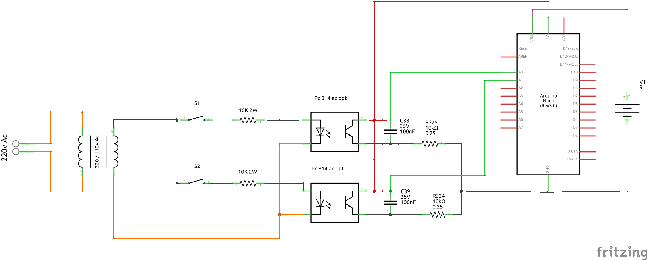
i am using the connections as below (schematic) to read the state (on/off) of some switches that have 110v ac from a transformer.
The switches are operating a machine and i just take a parallel output to monitor them with an arduino
The capacitors are just to filter a little the readings as without them i had a flickering time to time
(i had a suggestion from a member here to filter them with my code in order to remove the capacitors so it is something that will take as a consideration to my next pcb )
So after that short prologue i am asking your advice :
Do you know any other method or part / connection that could be used to my example ?
My schematic / connection is simple and cheap as i would like. The reason i am thinking to change it with something else is because i have to use the Big resistor in the input of the optocoupler.
I had to use a 10k resistor of 2W and are little big for my taste . i had to place them on stand-up position in order not take big space in my pcb design.
Also they get little hot ( 90-120 Celsius ) and that is why i am using the 2w resistors so not get fried
Looking at your choice of opto-couplers. They do make opto- couplers designed around an AC input. Just as an example:
When an opto-coupler uses a dingle internal LED it only conducts on alternate cycles of the AC waveform. For example only the positive cycles. This is why you needed the added capacitors. Next rather than one large high wattage resistor a popular choice is using two resistors as shown with the two 100K resistors illustrated above. While there are more ways to detect a mains AC voltage the opto-couplers are likely the simplest reliable way. I would choose this over relays and wall warts. Anyway if you take the optocoupler route thing about using AC optocouplers and two resistors.
")
