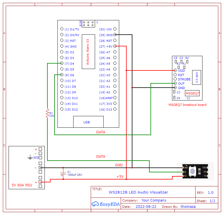
I made a schematic for an audio visualizer that uses an Arduino Nano V3 and a MSGEQ7 breakout board running a WS2812B (5M), all on 5v. I'd like to know what I can do to either improve the design of the circuit itself or the schematic to make it more readable.
How many LEDs in y0our WS28xx string ?
Depending on how they're arranged, youll probably see some benefit by injecdting power at multiple point along the line.
P.s. Please insert images directly into the topic, not links - because they don't appear in the email notofocations.
What exactly do you mean by this?
Reliable as in a larger mean time between failures, the correct use of the word.
Or reliable as in less noise on the output, not quite the correct word?
300 LEDs at 5m, I do have power injection planned I just didn't show it, I should have.
I did upload the image, I'm not sure what that's about. Sorry about that.
Readable as in the schematic itself, did I leave any information out that you think could be important, or did I leave in information that's not needed. the wiring crossing each other.
I haven't made many schematics before and from other questions I've asked people have suggested making schematics to help picture what I'm making. I looked up some stuff about making them but there seem to be many different ways of doing it, and I'm not sure what would be considered more correct.
Ah sorry, I am dyslexic and I miss read the word for reliable.
Yes a more readable schematic would involve fewer wire crossings. The need for all the wire crossings you have is due to you sticking to a physical representation of the pin order on the parts. A good schematic program will put the pins in a physical order by default and then allow you to change them as needs. Cheaper layout programs don't allow this and so the schematic is messy.
If you are drawing the schematic using a general purpose drawing package you can do this from the start. As long as all the connections are labelled and / or numbers you can place them wherever is more convenient to minimise wire crossings.
The use of Net Symbols also help. Always use these for power and ground. All net symbols of a specific type are all joined together, but don't overdo it or the schematic becomes impossible to read. For example you end up with a page full of rectangles an labels, this is the worst type of schematic ever.
Ground net symbols point down and power net symbols point up.
Great, thank you so much for the help. I'm dyslexic too so I totally get what happened, happens to me all the time.
Thanks for your time.
You are very welcome.
If you want to see examples of schematics I have drawn look at the hardware projects here:-
Transistor Tester
Figure 4 is a good example. I start with a block diagram and follow it with the schematic.
Note I have used the break line convention for wires that cross. That is when a wire needs to cross another wire, it approaches it and stops short of the line and starts again a short time after the line.
For starters, you can connect strobe and reset
Before "improving" the circuit and making it readable, it would be a good idea to check if it works at all. As @killzone_kid already wrote , the MSGEQ7 connection is not correct, you forgot the Strobe and Reset, so this scheme will not work.
Yeah for some reason I didn't think I needed to connect those, I looked at the datasheet for how it's supposed to work and realized that