HI, Guys i recently got a pair of apc220 wirelesses. I tried absolutely everything but they dont seam to work. I downloaded all drivers and programmed it using rf magic but no luck. Can anyone help me. when i unplug the usb the tx stops flashing when i upload a serial print hello every second!!!
U can safely use softwareserial with theese units..
attached file can be used insted of rf-magic (plug apc directly onto arduino from pin 8, pointing away from arduino)
..more info in the file itself..
Be sure to match communication speed with setup in apc
................
Theese modules works perfect!. I've done 2000m with 1/4wave sender antenna, homebuilt yagi as receiver antenna
_220config.ino (5.37 KB)
Hi thnks. For your reply. I have atwo questions. First, aftwr you upload the code and put the APC220 what go you do, how do you program it? And can you use three apc220 recieving info from the same pc??? Thankyou.
You have uploaded the code - then inserted apc200 from pin8 up (pointng away from arduino)
Now open serial monitor at 9600 baud.
The program have a menu built in (read it)
use command 'w' ...... to set up the two modules (one at a time) with IDENTICAL parameters
use 9600 air datarate and power 9, for long range communication
After setup: Use modules the same way as u use your serial ports...
Serial.println("commands:");
Serial.println(" r : Read apc220 radio config");
Serial.println(" e : go into echo mode: receive char, add 1 and return");
Serial.println(" n : no more echo - back to normal");
Serial.println(" w : Write apc radio config ...");
Serial.println(" 'W' FFFFFF R P B C - number of letters indicates precise number of digits" );
Serial.println(" FFFFFF: frequency: 434000 (434 MHz) range 418000-455000 ");
Serial.println(" R: Rf data rate - 1/2/3/4 equals 2400/4800/9600/19200bps");
Serial.println(" P: Radio output power - 0 .. 9 9 equals 13dBm(20mW).");
Serial.println(" B: UART baudrate - 0/1/2/3/4/5/6 equals 1200/2400/4800/9600/19200/38400/57600bps");
Serial.println(" C: Byte Chek Parity - 0/1/2 equals NoCheck(8N1)/EvenParity(8E1)/OddParity(8O1)");
Serial.println("");
Serial.println("Write example: w 434000 3 9 3 0 is...");
Serial.println(" 434,000 MHz 9600 baud in air, 20mW, 9600baud on UART, No Parity(8N1)");
Serial.println("After 10 seconds with no keyboard input we will emit a char every two second");
Thankyou I will tey this tomorrow and leav you feedback. Thankyou verry much. 1 last question can I use this point to multiple points the APC220?
any radio set to same parameters will 'hear' eachother and can communicate..
Hi, i am not quite understanding how do i access the built in menu?
..Then read the menu in reply #3
Try setting parameters like this
434,5 Mhz , 9600 baud air data rate, full power, 57600 system data rate no parity.
commando:
w 434500 3 9 6 0 then
You will get a response mirroring your input.
Now switch to second radio and repeat the same commando.
Tranceivers are now 'good to go'.
They connect to Arduinos with 4 wires. RX,TX,5V and GND
(use softwareserial and remember that RX on one end is TX on the other end.)
Hi thankyou very much i have successfully programed them do you have a code which i can use to test them. Thank you
Test..:
Connext pin 2(rx) to apc TX and pin 3 to apc RX (...and 5V and GND)
Receiver:
#include <SoftwareSerial.h>
SoftwareSerial apc(2,3);  // rx/tx
char txt;
void setup()
{
  Serial.begin(115200); // use full speed in serial setup
  apc.begin(57600); // match APC communication-rate
}

void loop()
{
  if(apc.available())
  {
    txt=apc.read();
    Serial.write(txt);
  }
}
for sender (test with sending characters - repeated)
#include <SoftwareSerial.h>
SoftwareSerial apc(2,3);  // rx/tx

char txt;
void setup()
{
  apc.begin(57600); // match APC communication-rate
}

void loop()
{
  for (txt='a'; txt<='z'; txt++)
  {
    apc.write(txt);
  }
  apc.println();
  delay(1000);
}
..i didn't test this myself, but its close..
HI, i only have one arduino so idealy the test is with the pc and arduino. And i dont think i have them connected!!!! Thankyou
Install "putty"
Open a serial connection at correct COMport, 57600, N81 to the local APC.
the text you send, will be replicated at the receiver (in Arduinos serial window)
Forget the sender program.
HI, fOR SOME REASON OR ANOTHER THEY CANT WORK. I am trying to send data via the usb converter to my apc connecter with the arduino uno!!! i am using the serial monitor, and i uploaded the receiver code on the uno. Please help me. I am great-full for the help you have given me so far.
I earlier mentioned putty.. forget it..
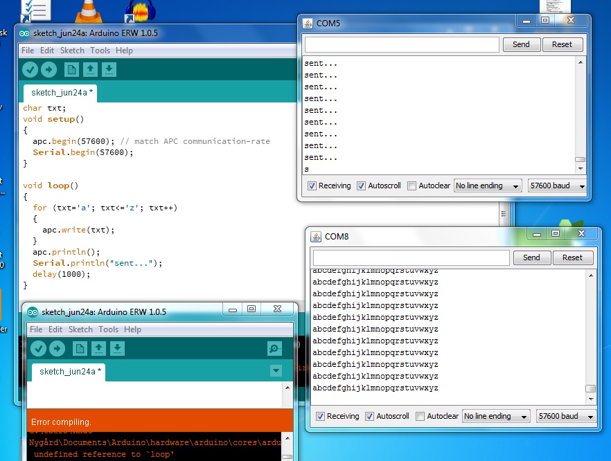
I run the Arduino IDE ( my COM5) with the test program U see in picture below.
Opened the serial monitor @ 57600 to se 'sent..' ... repeated.
......
Start a new copy of the arduino software, enter no program, but select correct comport (my COM8)
for the apc connected via the Silab inteface. set speed to match (57600)
The picture shows MY results. I'v got a functional transmission.
add theese
#include <SoftwareSerial.h>
SoftwareSerial apc(2,3);  // rx/tx
at program top
Via silab interface you mean the driver so it would look like a com port? And this is between pc and arduino?. How could you see what is recieved if the usb cable is disconnected from arduino?
arduino connected via usb (my com5)
adapter (silab following apc) at my com 8 in the second usb-port
study the picture again...(and post your positive results..)
Thank you very much your help is truly appreciated!!! I would suggest that anyone who has problems regarding these apc220's read this post. Thank you once again!! Now i need the to send characters from my laptop to my arduinos (i have 3). This is the arduino code. what modifications should i make? and once again thank you.
void setup() {
  // initialize serial communication:
  Serial.begin(9600);
   // initialize the LED pins:
      for (int thisPin = 2; thisPin < 7; thisPin++) {
        pinMode(thisPin, OUTPUT);
      }
}

void loop() {
  // read the sensor:
  if (Serial.available() > 0) {
    int inByte = Serial.read();
    // do something different depending on the character received.
    // The switch statement expects single number values for each case;
    // in this exmaple, though, you're using single quotes to tell
    // the controller to get the ASCII value for the character.  For
    // example 'a' = 97, 'b' = 98, and so forth:

    switch (inByte) {
    case 'a':
      digitalWrite(2, HIGH);
      break;
    case 'b':
      digitalWrite(3, HIGH);
      break;
    case 'c':
      digitalWrite(4, HIGH);
      break;
    case 'd':
      digitalWrite(5, HIGH);
      break;
    case 'e':
      digitalWrite(6, HIGH);
      break;
    default:
      // turn all the LEDs off:
      for (int thisPin = 2; thisPin < 7; thisPin++) {
        digitalWrite(thisPin, LOW);
      }
    }
  }
}
U've changed APC serial speed (earlier set to 57600)
I alse notice that u use the arduinos serial instead of softwareserial.
Doing so can interfere when upoading programs (this also use pins 0,1)
I use this code to control the onboard led.
After I upload the code, I switch comport - open serial monitor and send a '1' to turn on (other char turs off)
#include <SoftwareSerial.h>
SoftwareSerial apc(2,3);  // rx/tx
char txt;
void setup()
{
//  Serial.begin(57600); // use full speed in serial setup
  apc.begin(57600); // match APC communication-rate
  pinMode(13,OUTPUT);
}

void loop()
{
  if(apc.available())
  {
    txt=apc.read();
//    Serial.write(txt);
    digitalWrite(13,(txt=='1'));
  }
}
knut_ny:
U can safely use softwareserial with theese units..
attached file can be used insted of rf-magic (plug apc directly onto arduino from pin 8, pointing away from arduino)
..more info in the file itself..
Be sure to match communication speed with setup in apc
................
Theese modules works perfect!. I've done 2000m with 1/4wave sender antenna, homebuilt yagi as receiver antenna
rf magic is not working in my case
nice program for the uno
thanks