Good morning people . I'm having difficulty to applying an image (bitmap)
on my 128x128 OLED monochrome display. I created the logo (image)
in small format 80x43px , created the bitmap table by the site image2cpp , and copied
to the sketch.
Using the XBMP function, and setting the positions, width and height
of the image, it appears on the display, however irregular.
u8g2.drawXBMP(15, 50, 80,43 , logo_bits); // 80x43 format logo_bits
I noticed the following: the site image2cpp creates a sequential table (hex code) from left to right
. I manually inverted some lines hex code from right to left
and, magic, the image regularized !
Example of a sequence hex code line:
0x10 , 0x25 , 0x12 , 0x5c , 0x03 ....
inverting this sequence like this:
...0x03 , 0x5c , 0x12 , 0x25 , 0x10 .
Do not just invert the image ! it was necessary to reverse the sequence of
reading . I would be grateful if anyone has more details on this, or if
I'm using the wrong procedure. Thanks
I would expect 0x10 (b 0001 0000) to be "inverted" at 0x04 (b 0000 1000) and not just in reverse order (the bits representing pixels). Maybe I am not understanding "inverted" in this case. Pictures would be nice. Sounds interesting.
Invert means to turn upside down, this is not what you are doing.
To mirror is to get it to swap left and right.
Basically I think you have chose to use the wrong options when driving that site image2cpp.
However if this is not the case and the site has no such option then simply write a small code that reads those values into an array and outputs them in a suitable form so you can copy the output from the serial monitor and paste it in your code.
Post a link to the original JPEG, PNG, ... photo of your logo.
Most "bitmap" converters produce horizontal rows of bytes. Most Significant Bit first.
XBM format has horizontal rows with least sig bit first,
Different LCD, OLED, TFT, ... controllers organise their internal memory in different ways. For example bytes stored as 8 vertical bits per page on KS0108, ST7565, SSD1306, ...
U8g2 library supports regular horizontal bitmaps as well as XBM style horizontal format in SRAM. But only XBMP in Flash.
GFX libraries like Adafruit_SSD1306 supports regular horizontal bitmaps as well as XBM style horizontal format in SRAM. But only bitmap in Flash.
Your U8g2 library only does monochrome. i.e. your grayscale controller is wasted.
However it is simple enough to write a user function to display a grayscale picture and draw it on the SSD1327.
hey guys, I GOT IT!!!! I started to use the APP LCD image converter, which has all the options for scanning the image top/bottom, left/right ..etc, including the reordering of the byte bits, the latter solved the problem for me. Thank you all for your cooperation and attention. Thank you very much
Good Morning ! Perfect, I believe that many like me have encountered problems
when creating and printing images on the 128x128 monochrome OLED display.
Follow the link to dowload the very versatile App that allows all the options of
scan:
Here is also the Youtube link for a good explanation of use:
I take the opportunity to also ask two new questions:
1 - I created my bitmap by the application, reordering the sequence of bits in the byte
source:7-6-5-4-3-2-1-0 to 0-1-2-3-4-5-6-7 . The image appeared on the display,
however I noticed - flaws - spike: giving the impression that there is a gap (pixel) between
two consecutive bytes ! Why did this happen? ?
2 - David Prentice : However it is simple enough to write a user function to display
a grayscale picture and draw it on the SSD1327.
I ask for help on how to create this function. Is it appropriate to use the Adafruit bookstore?
or even by the U8g2 ?
by the 128x128 monochromatic OLED specification, it says it has 4 bits/pixel and can generate 16 shades of gray. how to do this in practice?
Thank you all for your collaboration , I was very excited about the progress
obtained with the help of this forum. Thanks
I don't know if the image was sent correctly, I copied and pasted it
The important thing is that the image you posted to that site should have been the same size as you wanted the bit map and be in the png format not a jpeg format.
It looks like the gaps have been created when the site attempted to scale your image you posted to the size of bit map you wanted.
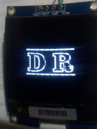
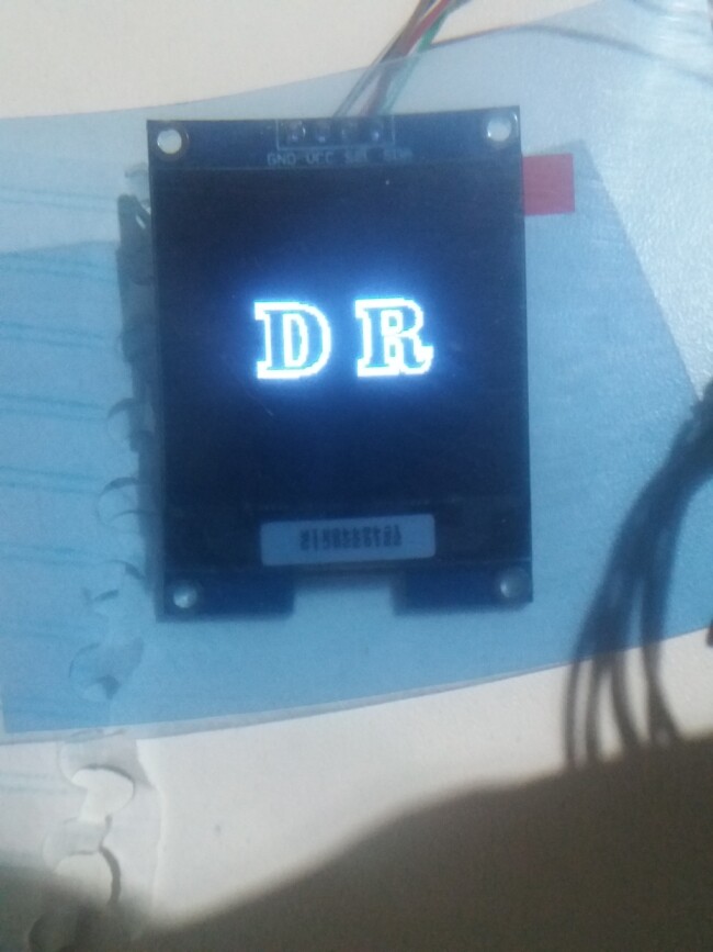
Good afternoon people ! I made changes to the DR image, saved it to PNG, applied it to the converter.
It got a little better, but you can still easily see that there is GAPS (pix)
between bytes !
In the application there is the adjustment of - preprocessing - TYPE: monochrome and just below the
options: Edge , Difusse dither , Orderer dither , Threshold dither. In all options the GAPS between
bytes persist ! .I'm starting to believe that I should rearrange the bits differently?
You hit the bullseye! I went to review the reordering of the bits in the byte ... and it was missing
reorder the zero bit!! There was the GAP among them !!! Now everything perfect!
Thanks for the help and observation friend ! ! saved me hours of research and
rework . Thanks !
Glad you got it working.
For the sake of completeness and to help others who have the same problem, could you explain exactly what you did to fix this.