Aquarium automation : Program Freezing Issues

Hello everyone,

I'm starting to get to know Arduino programming and prototyping electronics well, but I need help for the first time. That's why I'm reaching out to you, hoping to find a solution.

I'm currently automating various actions on my aquarium, namely:

  • Distributing fertilizer once a day using a peristaltic pump (stepper motor + DRV8825)
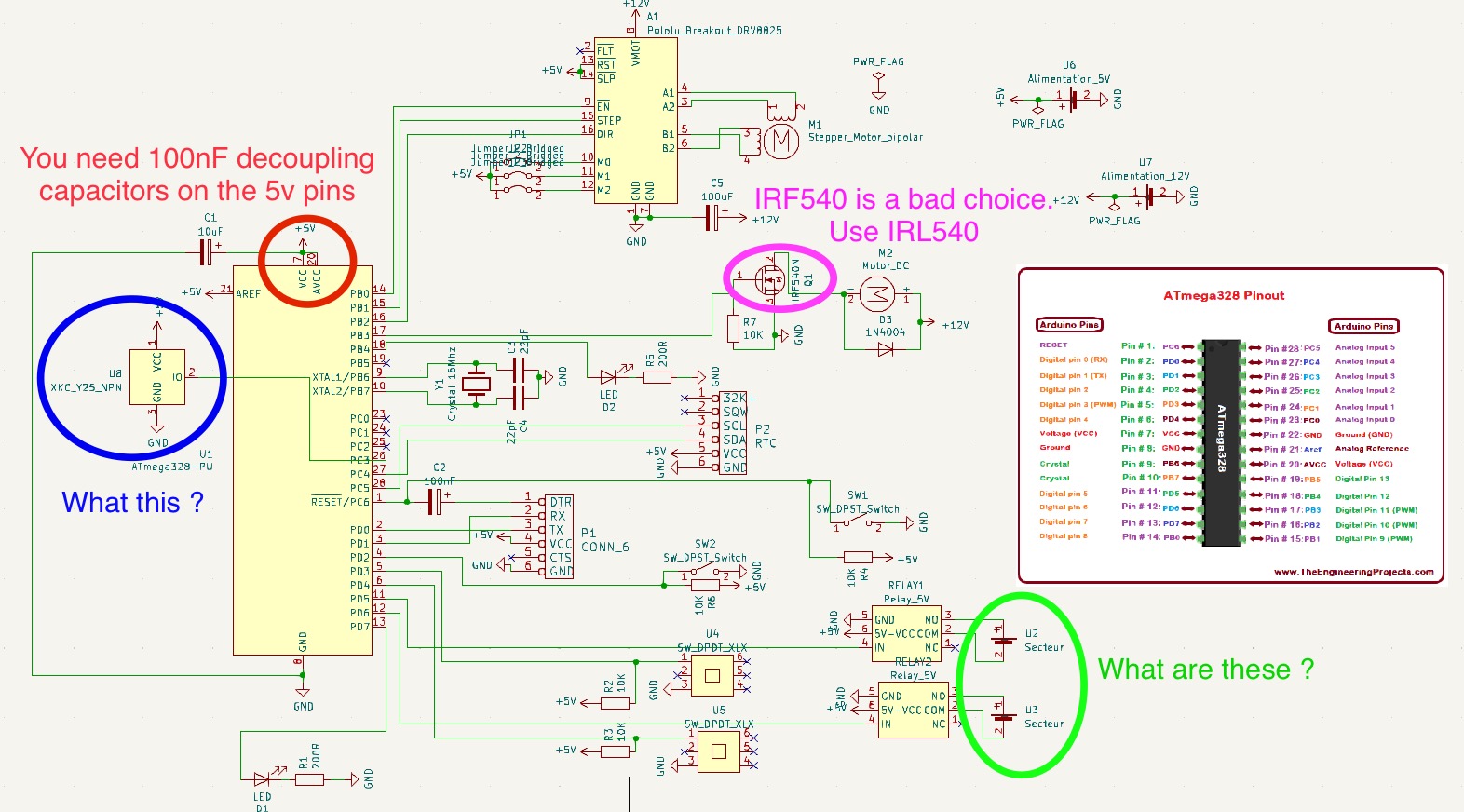
  • Filling the aquarium using a non-contact sensor Xkc-Y25-Npn and a peristaltic pump (DC motor + IRF540N assembly)
  • Turning on the light using a relay at time H
  • Turning on the CO2 using a relay at time H-30 min

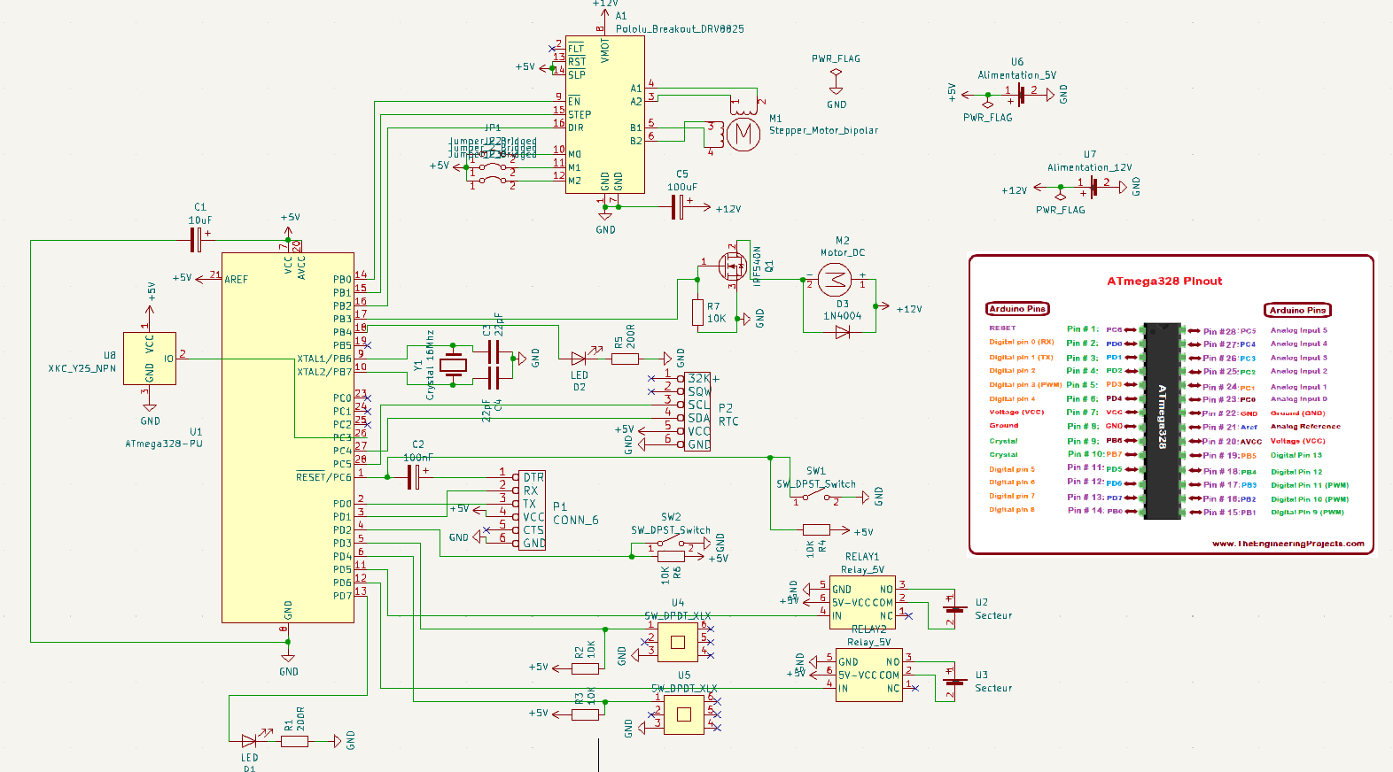
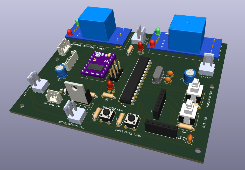
To do this, I've designed a PCB that controls all of this using an ATMEGA328P setup, an RTC module for time, and an FTDI for uploading the program. There are also 2 LEDs for debugging and the following buttons:

  • A button to reset the board
  • A button to update the time of the RTC module
  • A button to manually turn on the light and CO2 at the same time
    -A button to start the aquarium filling, which stops automatically

Unfortunately, I don't understand why, but the program freezes sometimes... So the light doesn't turn on, which is not good at all for my fish and plants if I go on vacation. In fact, I just left for 3 days, it bugged and I lost a fish... I feel like the problem occurs between turning on the CO2 and the LED, and it might be due to the RTC module, but I'm really not sure. I specify that the control and power circuits have two different power supplies. Does anyone have an idea of the origin of my problem?

Below is my program along with images of the electrical circuit. Feel free to ask if you have any questions or comments on my post, this is the first time I've done this! Thank you in advance!

#include <Wire.h>
#include <RTClib.h>
#include "AccelStepper.h"

RTC_DS3231 rtc;

#define dirPin 10
#define stepPin 9
int enablePin=8;
#define motorInterfaceType 1
AccelStepper stepper = AccelStepper(motorInterfaceType, stepPin, dirPin);

int pinNiveau=0;
int pinLedRouge=12;
int pinLedVerte=7;
int pinMoteur=11;

const int RelayLedPin = 6;
const int RelayCO2Pin = 5;

const int pinBout1=3; //LED
const int pinBout2=4; //OSMOLATEUR
const int pinBout3=2; //RESET TIME

int passageEngrais=0;

// Définir les moments de début et de fin pour l'allumage de la LED
int startHour = 13;   // Heure de début
int startMinute = 00;  // Minute de début
int endHour = 19;     // Heure de fin
int endMinute = 00;   // Minute de fin

int startHour3 = 00;   // Heure de début
int startMinute3 = 00;  // Minute de début
int endHour3 = 00;     // Heure de fin
int endMinute3 = 00;   // Minute de fin

int startHour2 = 18;   // Heure de début
int startMinute2 = 00;  // Minute de début
int endHour2 = 23;     // Heure de fin
int endMinute2 = 00;   // Minute de fin
int jour = 3;   // Jour (4 = jeudi / 0 = dimanche)
int passageNiveau=0;
int i=0;

void setup() {
  // put your setup code here, to run once:
  Serial.begin(9600); //initialise la communication série
  
  stepper.setMaxSpeed(1000);

  pinMode(pinMoteur,OUTPUT);
  digitalWrite(pinMoteur,LOW);

  pinMode(pinLedRouge,OUTPUT);
  digitalWrite(pinLedRouge,LOW);
  pinMode(pinLedVerte,OUTPUT);
  digitalWrite(pinLedVerte,LOW);

  pinMode(enablePin, OUTPUT);
  digitalWrite(enablePin, HIGH);

  pinMode(RelayLedPin, OUTPUT);
  digitalWrite(RelayLedPin, LOW);
  pinMode(RelayCO2Pin, OUTPUT);
  digitalWrite(RelayCO2Pin, LOW);

  pinMode(pinBout1,INPUT_PULLUP);
  pinMode(pinBout2,INPUT_PULLUP);
  pinMode(pinBout3,INPUT_PULLUP);

if (!rtc.begin()) {
    Serial.println("Couldn't find RTC");
    while (1);
  }
  else{
    delay(1000);
    Serial.println("Connection réussie");
  }

  if (rtc.lostPower()) {
    Serial.println("RTC lost power, let's set the time!");
    rtc.adjust(DateTime(F(__DATE__), F(__TIME__)));
  }

  afficherTemps();

  if (startMinute<30){
    startMinute3=60-(30-startMinute);
    startHour3=startHour-1;
  }
  else {
    startMinute3=startMinute-30;
    startHour3=startHour; 
  }
  if (endMinute<30){
    endMinute3=60-(30-endMinute);
    endHour3=endHour-1;
  }
  else {
    endMinute3=endMinute-30;
    endHour3=endHour; 
  }
}

void loop() {
  Serial.println("test");

  if (digitalRead(pinBout3)==0){
    rtc.adjust(DateTime(F(__DATE__), F(__TIME__)));
    afficherTemps();
    delay(1000);    
  }
  if (digitalRead(pinBout1)==1){
    verifHeure ();
  }
  else {
    digitalWrite(RelayLedPin, HIGH);
    digitalWrite(RelayCO2Pin, HIGH);
  }
  if (digitalRead(pinBout2)==1){
      if (analogRead(pinNiveau)>5 && passageNiveau==0){
        digitalWrite(pinMoteur,HIGH); //le moteur se lance
        digitalWrite(pinLedRouge,HIGH);
        passageNiveau=1;

      }
      if (passageNiveau==1 && analogRead(pinNiveau)<5){
        i++;
      }
      else{
        i=0;
      }
      if (i==5){
        i=0;
        digitalWrite(pinMoteur,LOW); // le moteur s'arrĂŞte
        digitalWrite(pinLedRouge,LOW);
      }
  }
  else {
    digitalWrite(pinLedRouge,LOW);
    verifNiveau();
  }
Engrais();
delay(1000);  // Attendez une seconde avant de vérifier à nouveau
}

////////////////////////////////////////////////////////////////////////////////////////////////////////////////////////////////////
void Engrais (){
  DateTime now = rtc.now();
  if (now.hour() == startHour && now.minute()==startMinute+5 && passageEngrais==0) {
  digitalWrite(pinLedVerte,HIGH);
  digitalWrite(enablePin, LOW);
  delay(1000);
  stepper.setCurrentPosition(0);
  while(stepper.currentPosition() != -60000)
  {
    stepper.setSpeed(-2000);
    stepper.runSpeed();
  }
  delay(500);
  stepper.setCurrentPosition(0);
  while(stepper.currentPosition() != 35200)
  {
    stepper.setSpeed(2000);
    stepper.runSpeed();
  }
  delay(500);
  stepper.setCurrentPosition(0);
    while(stepper.currentPosition() != 6000)
  {
    stepper.setSpeed(400);
    stepper.runSpeed();
  }
  delay(500);
  stepper.setCurrentPosition(0);
    while(stepper.currentPosition() != -2000)
  {
    stepper.setSpeed(-400);
    stepper.runSpeed();
  }
  delay(500);
  passageEngrais=1;
  digitalWrite(pinLedVerte,LOW);
  digitalWrite(enablePin, HIGH);
  }
  if (now.hour() == startHour+1){
    passageEngrais=0;
  }
}
void verifNiveau (){
  DateTime now = rtc.now();
 if (now.dayOfTheWeek()==jour && (now.hour() > startHour2 || (now.hour() == startHour2 && now.minute() >= startMinute2)) &&
      (now.hour() < endHour2 || (now.hour() == endHour2 && now.minute() <= endMinute2))) {
        //Serial.println(analogRead(pinNiveau));
  }
  else {
    passageNiveau=0;
    digitalWrite(pinMoteur,LOW); // le moteur s'arrĂŞte
  }
}
void verifHeure (){
  DateTime now = rtc.now();
  
    // Vérifiez si l'heure actuelle est entre 10h et 16h
  if ((now.hour() > startHour || (now.hour() == startHour && now.minute() >= startMinute)) &&
      (now.hour() < endHour || (now.hour() == endHour && now.minute() <= endMinute))) {
    digitalWrite(RelayLedPin, HIGH);
  }
  else {
    // Éteindre la LED
    digitalWrite(RelayLedPin, LOW);
  }
  if ((now.hour() > startHour3 || (now.hour() == startHour3 && now.minute() >= startMinute3)) &&
      (now.hour() < endHour3 || (now.hour() == endHour3 && now.minute() <= endMinute3))) {
    digitalWrite(RelayCO2Pin, HIGH);
  }
  else {
    // Éteindre la LED
    digitalWrite(RelayCO2Pin, LOW);
  }
}
void afficherTemps(){
  Serial.println("Date et heure d'initialisation :");
  DateTime now = rtc.now();
  Serial.print(now.year(), DEC);
  Serial.print('/');
  Serial.print(now.month(), DEC);
  Serial.print('/');
  Serial.print(now.day(), DEC);
  Serial.print(" ");
  Serial.print(now.hour(), DEC);
  Serial.print(':');
  Serial.print(now.minute(), DEC);
  Serial.print(':');
  Serial.print(now.second(), DEC);
  Serial.println();
}


  • Let’s start here.
    What do you think is happening with this ?

void loop() {
  Serial.println("test");

  if (digitalRead(pinBout3)==0){
    rtc.adjust(DateTime(F(__DATE__), F(__TIME__)));  //  <——<<<<<

  • How are you powering the 328 controller ?
  • What does this do ?
    stepper.setSpeed(-2000);

Hello LarryD!
First of all, thank you LarryD for your promptness! I'll address your questions:

  • To me, the line "rtc.adjust(DateTime(F(DATE), F(TIME)));" updates the time stored in the RTC module with that of the computer (used only when computer is connected). But in reality, I never actually touch that button because the RTC module drifts very little.
  • The "XKC_Y25_NPN" module is a non-contact liquid sensor that I attach to the outside glass of my aquarium to know when to stop filling it. Here's the module: [link]
  • The IRL module is more appropriate because it requires 5V at the "Gate," unlike the IRF which requires 10V, is that correct?
  • U2/Sector and U3/Sector are the 220V power supply for my LED and my CO2.
  • Isn't my 10uF capacitor a decoupling capacitor? Should I replace it with a 100nF one or add a second one?
  • The 328P is powered by a 5V / 2A source.
  • The line "stepper.setSpeed(-2000);" allows all the fertilizer in the tube to be drawn into the fertilizer reservoir to return to a reference position.

Googling a bit suggests it has an open-collector output. This implies its output should be pulled up to e.g. 5V. You need e.g. 10k between PC3 on your microcontroller and +5V. You have R2 through R5 which you can use as spares since they're redundant. Just make those pins "INPUT_PULLUP" to achieve the same. The resistors there don't hurt. The one across the sensor is necessary, however.


An attempt at a snubber circuit, perhaps? I don't see these electrolytic caps on the PCB, is that right? Any chance we can have a look at the PCB layout. The 3D render of the board looks nice, but doesn't say much.

In terms of coding, I'd have a look at the "state machine" concept. It's likely that somewhere in your program logic an unforeseen combination of conditions arises, causing your system to misbehave.

I'm very sorry to hear this.
Can you be more precise in how it malfunctioned, insofar it's possible to reconstruct this? Can you replicate the problem? If/when it occurs, does the system lock up altogether, or does it still function, but just behaves in a different way than you imagined?

PS: I would have considered making the lights come on when it's dark and maybe just leave out the whole RTC. Feed CO2 periodically (millis() is plenty accurate enough), switch lights based on input from e.g. an LDR/light sensor.

PPS: I once made an automatic pump switch for the drinking fountain of my cats. I made sure to include several safety mechanisms that run the pump if no motion is detected for more than a few hours. Knowing that I might have made a mistake somewhere, I made sure to err to the side of safety in the knowledge that turning the pump on a little too often wouldn't hurt, but failing to turn it on when it should have, could have killed a pet.

But to the compiler, __DATE__ and __TIME__ are constants that are baked into the code at compile time.

Yes, more or less correct.

Add 100nF at every Vcc pin of your 328P. I usually include one at AVcc as well.

  • To me, the line "rtc.adjust(DateTime(F(DATE), F(TIME)));" updates the time stored in the RTC module with that of the computer (used only when computer is connected). But in reality, I never actually touch that button because the RTC module drifts very little.
    This is the time and day when the sketch was compiled. Not a good thing to do here.
  • The "XKC_Y25_NPN" module is a non-contact liquid sensor that I attach to the outside glass of my aquarium to know when to stop filling it. Here's the module: [link]
    We see no link
  • The IRL module is more appropriate because it requires 5V at the "Gate," unlike the IRF which requires 10V, is that correct?
    Correct
  • U2/Sector and U3/Sector are the 220V power supply for my LED and my CO2.
    Let’s see links
  • Isn't my 10uF capacitor a decoupling capacitor? Should I replace it with a 100nF one or add a second one?
    10uF is okay, add the 100nF ceramic capacitors near the pins too.
  • The 328P is powered by a 5V / 2A source.
    Confirm this voltage with a voltmeter while the unit is running.
  • The line "stepper.setSpeed(-2000);" allows all the fertilizer in the tube to be drawn into the fertilizer reservoir to return to a reference position.
    This needs “type” positive long

  • Give us links to Relay1 and 2.
  • Show us good images of the actual wiring.
  • The 5V pin on P1 might back feed 5v to the PC when the FTDI is connected.

Thank you rsmls for your response, I will give you the necessary details!
For the Xkc-Y25-Npn sensor, it works perfectly with this connection so I don't think it's the source of my problem. However, I take note of the "INPU_PULLUP" mode which I knew existed but I wasn't sure if it worked with an ATMEGA328P alone (without an Arduino board). Regarding U2 and U3, it's just a JST connection from which I take one of the terminals of the 220V, so the symbol is incorrect. Sorry for the misunderstanding.

To provide more details, the problem I encounter is somewhat random, it can occur after 1 day or 7 days, which is strange.
I added a line "Serial.println("test");" precisely to better understand the origin of the problem.
Indeed, every time the program goes through this line, the green LED on the FTDI blinks. However, when the problem occurs, it stops blinking, so either the program is stuck somewhere (but I don't think so because there are no risky "While" loops), or the program has crashed as when I manually disconnect the RTC (which is why I think it comes from this component). Every time the problem occurs, the CO2 is on and the LED is not, so it must happen between the two. I have to have precise timing for the lighting and CO2 (and therefore use an RTC) because it's a aquascaping aquarium that requires very precise parameters to avoid algae (let me tell you, I have them for now).
Below is a photo of the setup (the Xkc-Y25-Npn and the RTC are connected below).

  • Kind of looks like EMI is causing this.
    Suggest you try to reproduce this by testing before coming to any conclusion.

  • Do you know what a State Machine is ?

  • AC and power cabling must be kept away from signal wiring, neaten your wiring to keep them away from the PCB too.

  • And suggest the OP never use while( . . . ), a State Machine conversion is highly recommended.
1 Like

Hello gregvda

Welcome to the best Arduino forum ever.

Check the conditions for exiting the while() loop:

	Line 156:   while(stepper.currentPosition() != -60000)
	Line 163:   while(stepper.currentPosition() != 35200)
	Line 170:     while(stepper.currentPosition() != 6000)
	Line 177:     while(stepper.currentPosition() != -2000)

You might design an open interval for exiting .

1 Like

Ok for "rtc.adjust(DateTime(F(DATE), F(TIME)))", I will look into removing that tomorrow.
The link for the XKC_Y25_NPN sensor: https://www.amazon.fr/dp/B088PGKPJ4?psc=1&ref=ppx_yo2ov_dt_b_product_details
Regarding U2 and U3, it's just a JST connection from which I take one of the terminals of the 220V, so the symbol is incorrect. Sorry for the misunderstanding.
Otherwise, I'm at 4.90V at the 5V terminals.
For the line "stepper.setSpeed(-2000);", it works very well so I don't think it's a problem...
The link for the relays: https://www.amazon.fr/gp/product/B07VS7C7YC/ref=ppx_yo_dt_b_asin_title_o09_s00?ie=UTF8&psc=1
"The 5V pin on P1 might back feed 5v to the PC when the FTDI is connected.": We agree that it's not a problem if I disconnect my 5V power supply when I upload a program with the FTDI, right?

  • Positive numbers only.
  • Or, cut that 5V pin off the FTDI or remove your PCB female 5V pin

I confess I haven't looked into the issue of EMI yet, I'll keep that in mind to test soon. I'm not familiar with what a "State Machine" is unfortunately, but I'll also look into that! However, I've already coded an Arduino program asynchronously with timers and events (but it's been a while). I know it allows you to avoid "delay" statements which aren't clean in Arduino programming, but my program is still quite simple so I didn't think I'd need that kind of thing.

"stepper.setSpeed(-2000);" : Of course, you're right, sorry about that. I'll change that.

I'll make some modifications tomorrow and get back to you!
Thanks again!

Hi paulpaulson, thank you for joining the discussion.
For me, it's an open loop, nothing verifies that the motor reaches its final position from a physical point of view.
So from a programming perspective, it will inevitably reach its setpoint.
Moreover, these "while" loops come after the "bug", so I don't think they are the source of the problem.
Do you agree?

1 Like

I also don't think it's the cause. The documentation I found initially mentioned it's an open collector output, but I just did some additional googling that shows the collector is internally pulled up to VCC on the sensor. So don't worry about it.

As to the stability issue: try running a simulated program that cycles through everything faster so you can stimulate a longer timescale. See if you can make the problem appear more often this way so you have better ability to witness/analyze it. Troubleshooting a problem you have to wait for days for it to appear is often tricky.

Hello everyone!

I've taken into account your feedback to modify the next version of my PCB, including relocating the relays far away from the control circuit and adding a 100nF capacitor. I would like to know what you think about it? In any case, I had to redo it for other reasons, so I might as well incorporate your recommendations :wink:

I will take care of converting the code into a "state machine" if my issue persists.


  • Every 5v pin on the controller needs its own 100nF decoupling ceramic capacitor; as close to the pin as possible.

  • The IRF540 still needs to be an IRL540.

  • The 5v pins on the relays should have a 100uF going to GND (reservoir capacitor) i.e. next to the 5v pin.

  • The relay modules could be 90° i.e. over the PCB.

  • Suggest you add a jumper on the FTDI 5v pin.
    Pulling the jumper disables 5v connection from the FTDI.

  • SW1 and SW2 are labeled DPST.

Hi and thanks again for your response! Here are the latest things I've done:

  • I added two 100nF capacitors so that there's one on the Aref, one on the AVCC, and one on the VCC.
  • I added two capacitors on the relays.
  • I replaced the IRF540N to IRL540N.
  • I changed the names of the buttons to make it cleaner.
  • I removed the FTDI jumper.

I hope we're good to go this time, just need to test it out!

  • Was suggesting Vcc on the FTDI header connect to +5v through a jumper option.
    That way you can easily isolate PCB 5v from PC 5v.