COuldnt you use a dual axis Gyro only and skip the accelerometer?
just wondering about wayts to simplify.
COuldnt you use a dual axis Gyro only and skip the accelerometer?
just wondering about wayts to simplify.
Hi all,
You may be interested to know about the Kalman filter, I have used kalman filters to remove the noise and drift from the gyros and merge the readings with the angle computed from the accelerometers.
There is code available for 6DOF computation in the Arduino Helicopter Autopilot thread.
http://www.arduino.cc/cgi-bin/yabb2/YaBB.pl?num=1229733416
This may help - may not... depends how much headache you are prepared to put up with! It's certainly not simple, but the results are spectacularly improved.
Hope that helps,
Ed
COuldnt you use a dual axis Gyro only and skip the accelerometer?
Gyro = expensive, complicated and drifts
Accelerometer = cheap, simple does not drift
The point was to only use gyro on the axis that can only be detected by the gyro, for everything else use the accelerometer.
You may be interested to know about the Kalman filter, I have used kalman filters to remove the noise and drift from the gyros and merge the readings with the angle computed from the accelerometers.
There is code available for 6DOF computation in the Arduino Helicopter Autopilot thread.
http://www.arduino.cc/cgi-bin/yabb2/YaBB.pl?num=1229733416This may help - may not... depends how much headache you are prepared to put up with! It's certainly not simple, but the results are spectacularly improved.
Hope that helps,
Hey,
I've been following your thread with interest! I've started to look a little bit into the Kalman filter. Right now the problem is the gyro axis is orthogonal to the accelerometer axes, so there is nothing to correct the gyro with, unless I add a compass as well... So without the "merging" part, the Kalman filter is not much more useful than a simple high-low pass filter... Saying that, it might be possible to bring some of the accelerometer data in for correction when the tilt or roll of the head is large enough, so I might need to see how you did it in arduino code sometime!
Also I think your PPM reading thing will be useful too, for my own autopilot/OSD thing!
Thanks,
-Z-
Thank you to Zitron for the inspiration for my project, from which I intend to make the head-tracker, air mouse, and mini-Segway (perhaps transferred to fullsize DIY Segway our FIRST Robotics team is building).
I am using the Sparkfun Freeduino and Prototype shield, and from Pololu the inexpensive LISY300AL gyro (300 degrees/second) and MMA7260QT 3-axis accelerometer breakout boards which have integral regulators, so can be powered directly from the Arduino 5V supply.
I started my code based on the Arduino sample ADXL3xx, and have it working. The outputs are filtered using the algorithm from the DIY Segway project, it appears to work well.
Offsets are calculated at runtime, using the average of the first 500 samples. Once the offsets have been calculated, the program outputs them at regular intervals in a comma-separated string.
  if (millis_time >= millis_88Hz) {
    millis_88Hz = millis_time + freq_88Hz;

    rraw = analogRead(rpin);

    if (offsetreadings > 0) {
      rtot = rtot + rraw;                // long-term calculation of offset
      rtot_count++;
    }
    else if (offsetreadings == 0) {
      roff = int(rtot / rtot_count);     // permanent offset based on average
    }
    else {
       rread = rraw - roff;
       rfilt = rfilt * 0.9 + float(rread) * 0.1;
    }
  }
At first I was just reading the analog inputs as fast as possible, but then got reading the datasheets which state that gyro updates are at 88 Hz on the chip, and accelerometer outputs at 350Hz and 100 Hz for the z-axis. So there are separate 88, 100, and 350 Hz timers to read each input at the rates mentioned on the datasheets. Is this overkill? Am I misunderstanding what the datasheets are saying?
  if (millis_time >= millis_88Hz) {
    millis_88Hz = millis_time + freq_88Hz;

    rraw = analogRead(rpin);

    if (offsetreadings > 0) {
      ztot = ztot + zraw;                // long-term calculation of offset - not accurate enough
      ztot_count++;
    }
    else if (offsetreadings == 0) {
      zoff = int(ztot / ztot_count);     // permanent offset based on average
    }
  }
Now I'm going back over Zitron's code looking at the filter algorithm, and noticed this statement:
analogReference(EXTERNAL);
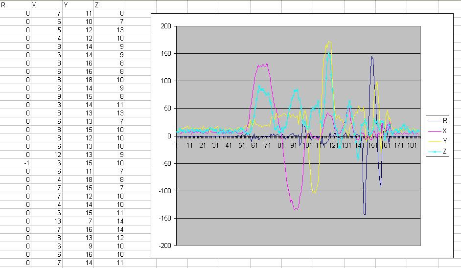
I have noticed that the offsets are calculated differently, each time I reset the Arduino, and sometimes not quite well enough. You can see the effect on the chart, the XYZ values should be centered on the zero axis but are slightly above.
I've wondered whether there is some voltage floating somewhere to cause this. I'm a programmer and ALWAYS suspect the electronics ![]() NEVER my (current!) understanding of the problem.
NEVER my (current!) understanding of the problem.
Anyway, I am hoping the analogReference() function will provide more consistent results. But looking at the Arduino page about analogReference, there is mention of using a 5K resistor to connect voltage inputs to the Arduino. I have been using straight wiring directly from the Pololu breakout board outputs to the analog in pins, I guess it's time to replace these with 5K resistors - before I add a analogReference(INTERNAL) line to my code?
Next I will be using Zitron's code to convert the filtered unit-less values I am outputting now, to degrees, Elevation, and Roll. Maybe someone can advise what to do with the Z-axis value ... at the moment it is only telling me whether the project is upside down or not.
Another issue - how to separate Elevation and Roll from the 'impulse acceleration' caused by motion? I would like to provide separate outputs to the computer for these, and have been trying to do this in the Visual Basic program with little success.
Mike
Hi Mike,
I've not seen your data sheet, but I think those output frequencies are usually the maximum frequencies the sensors can be use to detect. If your thing is vibrating at higher than 88Hz, the gyro will not be able to respond fast enough to output the true motion. So there it is probably better to try to sample at lower frequencies than the maximum.
I am sampling everything at 100Hz, which I think is more than enough, you should be able to get away sampling everything at 50Hz.
The analogReference(EXTERNAL) is used to map the voltage from the sensor to the analogRead() function for increased resolution. Because my arduino is at 5V, without the external reference, analogRead returns 1024 for 5V, 0 for 0V, but the maximum output of my sensors are 3V, so I'm only using 3/5th of the full resolution, by sending 3V to the analogue reference pin, and setting the analogReference(EXTERNAL), the voltages are mapped: 0V -> 0, 3V -> 1024.
Now, the 5K resistor is use to connect the external voltage to the analogue reference pin, not the analogue in pins!
Next I will be using Zitron's code to convert the filtered unit-less values I am outputting now, to degrees, Elevation, and Roll. Maybe someone can advise what to do with the Z-axis value ... at the moment it is only telling me whether the project is upside down or not.
You can use the arctan2(x,y) function like in my code to combine the Z value with X or Y, this way you can get a full +/-180 dgr values, with better accuracy.
Another issue - how to separate Elevation and Roll from the 'impulse acceleration' caused by motion? I would like to provide separate outputs to the computer for these, and have been trying to do this in the Visual Basic program with little success.
If the accelerometer is all you have, you can't! If you have the gyro working, you can use some sophisticated mathematical filters to reduce the effect of motion by combining the gyro and accelerometer readings. I am in the process of trying to do this myself...
Cool project, good luck!
-Z-
Oh, by the way, if you need a way of plotting the data in real time, I'm written a program that takes a line of comma separated serial data and plot it:
Right now it's hard coded to use baud rate of 57600. It plots 4 channels at the same time. The format of the data is:
channel1,channel2,channel3,channel4\n
If you have less than 4 channels you need to use place holders like:
channel1,0,0,0\n
Cheers,
-Z-
Thanks Z.
That 5K resistor thing was really nagging me, it didn't make sense and also I feared it might mess with the RC filter already on the gyro/accelerometer outputs. So after pondering the situation today and re-reading everything again, twice - I did discover that the resistor is to be added to the VREF pin, not to every input pin. I didn't have a 5K, so I used a 4.7K and wired it up to the 3.3V produced by the Arduino's own regulator. The ones on the gyro and accel boards seem to be more accurate, but they aren't the same and I couldn't decide which to use:
Arduino 3.345V (3.266 mV/unit)
Gyro 3.305V (3.227 mV/unit)
Accelerometer 3.293V (3.215 mV/unit)
Now that the thing has been running with analogReference(EXTERNAL) without magic smoke, I'll probably use the gyro 3.3V output as it's the closest to ideal.
I've been using Hyperterminal to collect the CSV and Excel to chart, and wrote a VB program as well - it doesn't graph, but does use slider controls so you can see what is going on, and I'm playing around with drawing lines on a PictureBox to visualize how the sensor is oriented. That will be easier once the code is outputting proper angles.
Offsets - :![]() hmmph - of course it was my code that calculated them wrongly (far too few samples), I changed my too-clever "offsetcount" method to a time measurement calibration instead ... I've tried 1, 5 and 10 seconds it doesn't seem to make much difference to the offsets, which pretty much take all the sensors to zero with no-motion - aside from the gyro drift of course.
hmmph - of course it was my code that calculated them wrongly (far too few samples), I changed my too-clever "offsetcount" method to a time measurement calibration instead ... I've tried 1, 5 and 10 seconds it doesn't seem to make much difference to the offsets, which pretty much take all the sensors to zero with no-motion - aside from the gyro drift of course.
Thanks for your insight about responsiveness - I removed my special timer code and the results were pretty well the same as before.
As for the 'impulse' acceleration and separating that from the physical position of the device, I've been playing around in the VB program and taking the difference between successive readings as the impulse, and trying to subtract an accumulation of impulses from the current value.
Do you know how to post images?
You have to host the file on some other server, and use the image tag...
Obvious - so why was I trying to use the media tag :-[
Good progress today. It outputs rotation in degrees-per-second units, and pitch/roll/vertical angle in degrees.
All credit for pitch/roll goes to the post at http://www.arduino.cc/cgi-bin/yabb2/YaBB.pl?num=1208368036 see Post #3, the method works great.
// gyro range in degrees - this gyro is +/- 300 degrees/second
#define GYRO_RANGEDEGREESPERSECOND  600.0

float rdegreeunits = 1024.0 / GYRO_RANGEDEGREESPERSECOND;      // 1.706 A/D units per degree-per-second (which is the output from the gyro)

// accelerometer calibration - output the filtered values while pointing and rolling the device to its extremes
// GMAX maximum reading (+1g) GMIN minimum (-1g)
// gyro range in G (gravity acceleration) - the gyro is jumpered to use low range which is +/- 1.5 G

#define XGMAX 272
#define XGMIN -283
float xg_constant = 0;
float xg_b = 0;

#define YGMAX 284
#define YGMIN -273
float yg_constant = 0;
float yg_b = 0;

#define ZGMAX -556
#define ZGMIN 0
float zg_constant = 0;
float zg_b = 0;


float xgs;
float ygs;
float zgs;

float rdegreespersecond = 0.0;
float pitchdegrees = 0.0;        // angle of X-axis to the ground
float rolldegrees = 0.0;         // angle of Y-axis to the ground
float thetadegrees = 0.0;        // angle of Z-axis to the ground
     // scale the gyro A/D value to degrees per second - gyro already outputs those units, so this just scales for the 0-1023 A/D range

     rdegreespersecond = rfilt / rdegreeunits;      // printed output looks about right

     // scale the accelerometer values to pitch and roll
     //     see (http://tom.pycke.be/mav/69/accelerometer-to-attitude)
     //     but these calculations are from jmknapp's post at http://www.arduino.cc/cgi-bin/yabb2/YaBB.pl?num=1208368036
     //
     //  gx = kX + b
     //  where k = 2 / (xrange) = 2 / (272-(-283) = 0.0036
     //        b = 1 - k * xmax = 1 - 0.0036 * 272 = 0.0208
     //        X is the accelerometer reading
     //
     //  if the device is held still and reasonably level during calibration, it will produce output like this:
     //    0,91,89,178   (0 deg/sec rotation, 91 deg pitch, 89 deg roll, 178 deg from vertical
     //  how great is that!

     xg_constant = 2.0 / float(XGMAX-XGMIN);
     xg_b = 1 - xg_constant * XGMAX;
     xgs = xg_constant * xfilt + xg_b;

     yg_constant = 2.0 / float(YGMAX-YGMIN);
     yg_b = 1 - yg_constant * YGMAX;
     ygs = yg_constant * yfilt + yg_b;

     zg_constant = 2.0 / float(ZGMAX-ZGMIN);
     zg_b = 1 - zg_constant * ZGMAX;
     zgs = zg_constant * zfilt + zg_b;

     pitchdegrees = atan2( xgs, sqrt( sq(ygs) + sq(zgs) ) ) * 57.296 + 90;     // pitch angle of x-axis relative to ground
     rolldegrees = atan2( ygs, sqrt( sq(xgs) + sq(zgs) ) ) * 57.296 + 90;      // roll angle of y-axis relative to ground
     thetadegrees = atan2( sqrt( sq(xgs) + sq(ygs) ), zgs ) * 57.296;          // angle of z-axis relative to gravity


     PrintTerms( int(rdegreespersecond), int(pitchdegrees), int(rolldegrees), int(thetadegrees) );
I posted the PDE at http://www.sunsys.net/arduino_images/ if anyone is interested.
Next I'll get back to trying to understand what's going on in Zitron's gyro drift filter.
I found SelmaDAQ which lets you run Excel and live graphs of the Arduino CSV output.
By the way, since I "fixed" the calculation of offsets (see code above) the gyro drift appears to be gone.
I did not need to apply any of the filtering (gAlpha calculations) to achieve that.
Assuming I am correct in this, there is a difference between your offset calculation (which averages many hundreds of samples, read as quickly as possible) and mine (which reads many hundreds of sample, over a fixed time interval - 5 seconds).
You may be interested in this paper http://www.cl.cam.ac.uk/techreports/UCAM-CL-TR-696.pdf which describes use of current MEMS devices for inertial navigation ("strap-down INS") and the negative impact that the relatively large errors of today's MEMS devices has on that application.
I came across this while looking for solutions to obtaining speed and distance from acceleration. My current code for this is:
       old_accel = xaccel;
       xaccel = xfilt * xg_per_unit * SPEEDUNITS;
       xdeltav += (xaccel - old_accel)/2;
       xspeed += xdeltav;
       xdistance += xspeed;
See my code submissions previously for the meaning of the variables.
The calculations seem to work out, but even very tiny amounts of tilt cause the appearance of acceleration due to gravity. I somehow need to factor this out, perhaps by using the pitch, roll, and vertical values calculated earlier to measure the amount of tilt and do some calculation to remove it from the acceleration xfilt. Or perhaps by simply ignoring small variables (+/- 2 or 3 degrees) of tilt.
lol sorry if i'm coming out of nowhere, but where did you stumble on those part's you showed in your first post? i'm looking for an inexpensive gyro or accelerometer... i'm on a budget lol
Big,
See this: RC Groups - View Single Post - DIY head tracker from cheap heli gyro (seems to work!)
Mike,
Thanks for the paper, interesting reading!
I had to use some high pass filter for my gyro because not only does it need to be calibrated at the start, it will drift slowly due to temperature, voltage changes. If you have a better quality gyro, it might not be a huge problem.
As far as the sampling is concerned, I think the number of samples is less important than how long you sample. So your method is probably better, I was lazy so I used a simple for loop!
Cheers,
-Z-
I think you are right about the gyro quality, I have used a different one in our FRC group and it does drift. In fact it also features a temperature output - which seems like a useless thing, but I suppose it could be used to calculate a temperature-compensation value.
There is another paper in the DIY Segway project about using gyro and accelerometer together to improve accuracy, without sacrificing speed or needing to compensate for drift. Both high-pass and low-pass filters are used, in something he calls a 'complementary filter'.
Go to http://web.mit.edu/first/segway/#misc, click on Technical Documentation, download the segspecs.zip file, open filters.pdf.
Here is my Visual Studio 2005 project which interfaces the Arduino to Flight Simulator X, to control the cockpit camera - pitch, roll, and rotation.
It communicates with FSX using SimConnect which is supplied on the FSX SDK - that is found on the FSX Deluxe CD.
http://www.sunsys.net/arduino_images/Cockpit Camera.zip