Hallo Marcel
You are quite right in feeling frustrated with so many contradictions regarding the ground plane under the crystal. Perhaps this reply could put your concerns to rest and I will attempt to keep it as simple as possible.
We note that the piezoelectric crystal is seald within a metallic "can" which can be classified as a "Faraday cage". Therefore any electrical fields inside the "can" are unable to interact with the outside world. As a result of this, the presence of a ground plane under the crystal will have no effect on its performance.
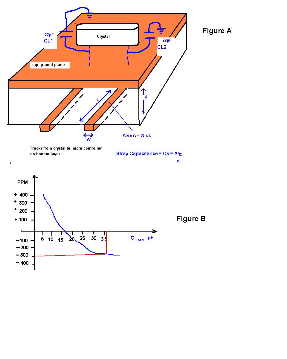
So now we have to look for other variables that can affect the performance of the crystal. I want you to look at the attached figure.
In Figure A, the crystal interacts with the outside world by means of electrical tracks to the microcontroller. Also we note that the crystal has 22pF on each leg. Lets call these capacitors CL1 and CL2. These capacitors are reccomended by the manufacturer and add LOAD capacitance to the crystal. The size of the LOAD capacitance determines how much the frequency of the crystal is PULLED. The amount by wich a crystal is pulled is called the PPM value or Parts Per Million.
For example, if a 16MHz crystal is pulled off by +100PPM, it means that:
for every 1 million Hertz (1MHz), the frequency is pulled off by +100Hertz
therefore for 16 million Hertz (16MHz), the frequency is pulled off by +1600Hertz
We now have to introduce one final variable. Its the stray capacitance Cs. This stray capacitance Cs (in pF) is calculated by the formula Cs= (AE)/d
where A is the area of the track that joins the the pin of the crystal to the leg of the micro
(Area A = W x L)
E is the dielectric constant of the printed circuit board (typically = 4 for fiberglass)
d is the hight of the printed cricuit board (I assume 1.6mm)
So to sum it up nicely, the total load capacitance is:
C Load = [ (CL1 x CL2)/(CL1 +CL2) ] + Cs
Once you have the value of C Load, you use the crystal data sheet to see by how many PPM the crystal will be PULLED as shown in figure B.
The point I want to stress is that the value of C Load is in part dependent on the stray capacitance Cs.
If you take away the ground plane, Cs will diminish to zero because the signal tracks at the bottom layer will have no copper ground plane to interact with.
Lets put some numbers to quantify this. Assume that we pour a ground plane on top and we have a track of width 1mm and length 10mm. Assume the dielectric constant "E" = 4 and the height of the substrate "d" is 1.6mm. The stray capacitance is:
Cs= (AE)/d =(WxL)(E)/d = (1x10)(4)/(1.6) = 25pF
Now we complete the whole loading capacitance equation:
C Load = [ (CL1 x CL2)/(CL1 +CL2) ] + Cs
C Load = [ (22 x 22)/(22 +22) ] + 25
C Load = [11] + 25
C Load = 36pF
Looking at the graph in figure B we see that the 16MHz crystal is pulled off by -300PPM or -4.8KHz to be exact
To conclude, we can say that the ground plane DOES have an effect on the crystal's frequency of operation. The ground plane will introduce stray capacitance Cs which in turn will affect the PPM value. The question you have to answer is whether the PPM deviation of the crystal falls with in your operational specifiations.